Dolence
-
Posts
21 -
Joined
-
Last visited
-
Days Won
2
-
Moderator, please delete this topic. It's been a long time and I couldn't even initialize this display properly. I'm abandoning this project. Thanks.
-
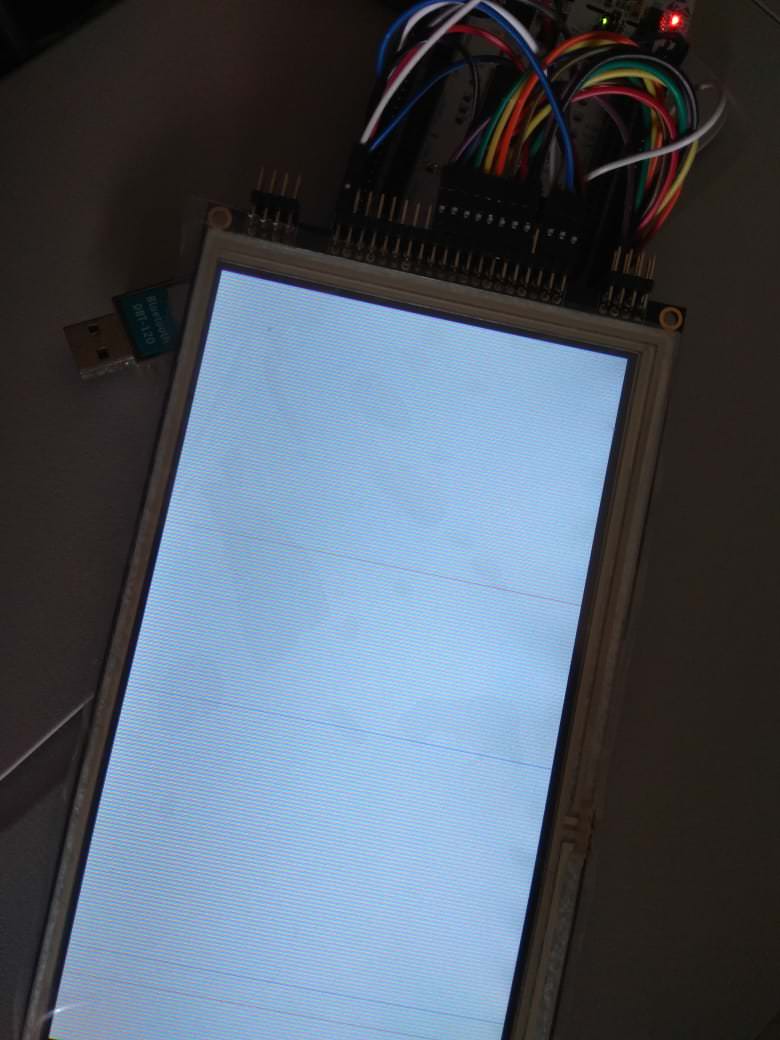
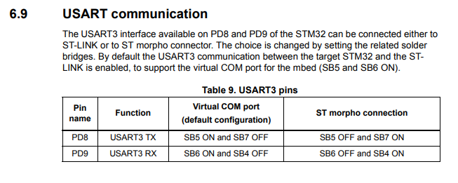
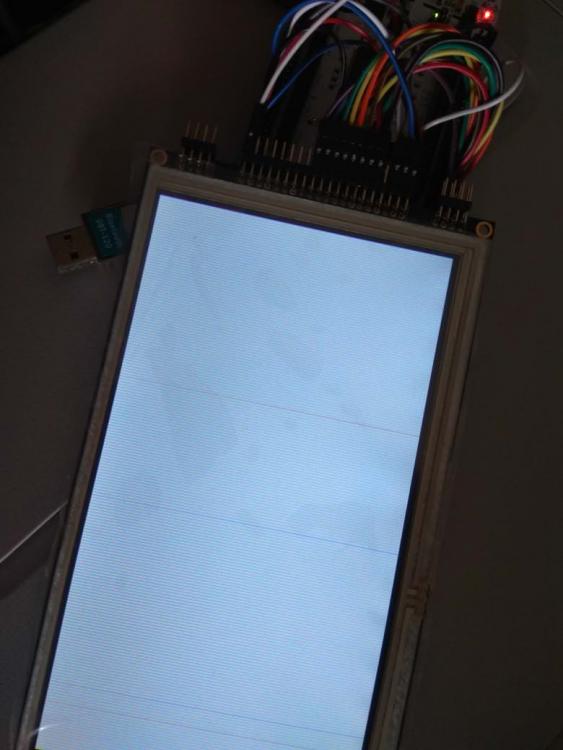
OK, so after testing the display in GPIO mode using an Arduino Mega and stating my display is fine I did some tests. I made a new STM32CUBEMX project using my board (nucleo-f746zg) with all the uneeded periperals left aside. I then set the FMC options reflecting my actual wiring: CS on NE1 Memory Type: LCD Interface LCD Register Select: A16 Data: 16 bits I have my display wired as this: ----- STM 32 ---------- SSD1963 ---- PD6 LCD_RESET /RESET PD4 FMC_NOE E_RD PD5 FMC_NWE R/W_WR PD7 FMC_NE1 /CS PD11 FMC_A16 D/C PD14 FMC_D0 DB0 PD15 FMC_D1 DB1 PD0 FMC_D2 DB2 PD1 FMC_D3 DB4 PE7 FMC_D4 DB4 PE8 FMC_D5 DB5 PE9 FMC_D6 DB6 PE10 FMC_D7 DB7 PE11 FMC_D8 DB8 PE12 FMC_D9 DB9 PE13 FMC_D10 DB10 PE14 FMC_D11 DB11 PE15 FMC_D12 DB12 PD8 FMC_D13 DB13 PD9 FMC_D14 DB14 PD10 FMC_D15 DB15 It's important to say that in NUCLEO board I had to desolder the bridges SB5/SB6 to be OFF and let SB4/SB7 in ON to be able to use USART3 pins as GPIO since they are tied to ST-LINK as default. Display initialization sequence is ripped from Arduino manufacturer example. I made a test to see if A16 state is being changed on DATA/CMD writes and it's working as expected. I have tried every FMC timing and mode I could find. Most of the time I got only a white background with thin static vertical colored lines. Some times it looks like it has been initilized but only portion of the screen is covered by a weird kahki background with some colored pixels sparkled over it. Suspecting it could be some kind of under powering issue (big display + backlight + nucleo board) I made a separete power 12V power source to nucleo board (over VIN) and 3.3V to display/backlight. I'm using very short arduino style jumper wires. It worked in slow bit banging mode on Mega example. I'm not sure the higher speed of STM32 is an issue since I saw people using long flat cables like those used in the old days IDE drives. I don't know what to try anymore. It's very hard to find a working example using FMC and STM32+SSD1963. I think F7 FMC have something different that I may be missing. I'm on this for days, no big progress so far. I know it's a community forum, most of you have been busy with your own tasks, but please, help me to figure this out.
-
Using an arduino mega and TFT library provided by manufacturer the display worked. It isn't defective. I don't even know if I'm glad or sad LOL.
-
Changed my nucleo to external 5V power, checked all the wiring lines one by one 3 times using an multimeter to be sure, tried to send init commands directly in a barebone fashion. Nothing produced any different result. I noticed my display has come with a 20mhz crystal instead a 10mhz as mentioned in gdisp_lld_SSD1963.c driver file PLL and SYS clock configurations, don't know if it could be the cause. I'm starting to suspect my display is defective.
-
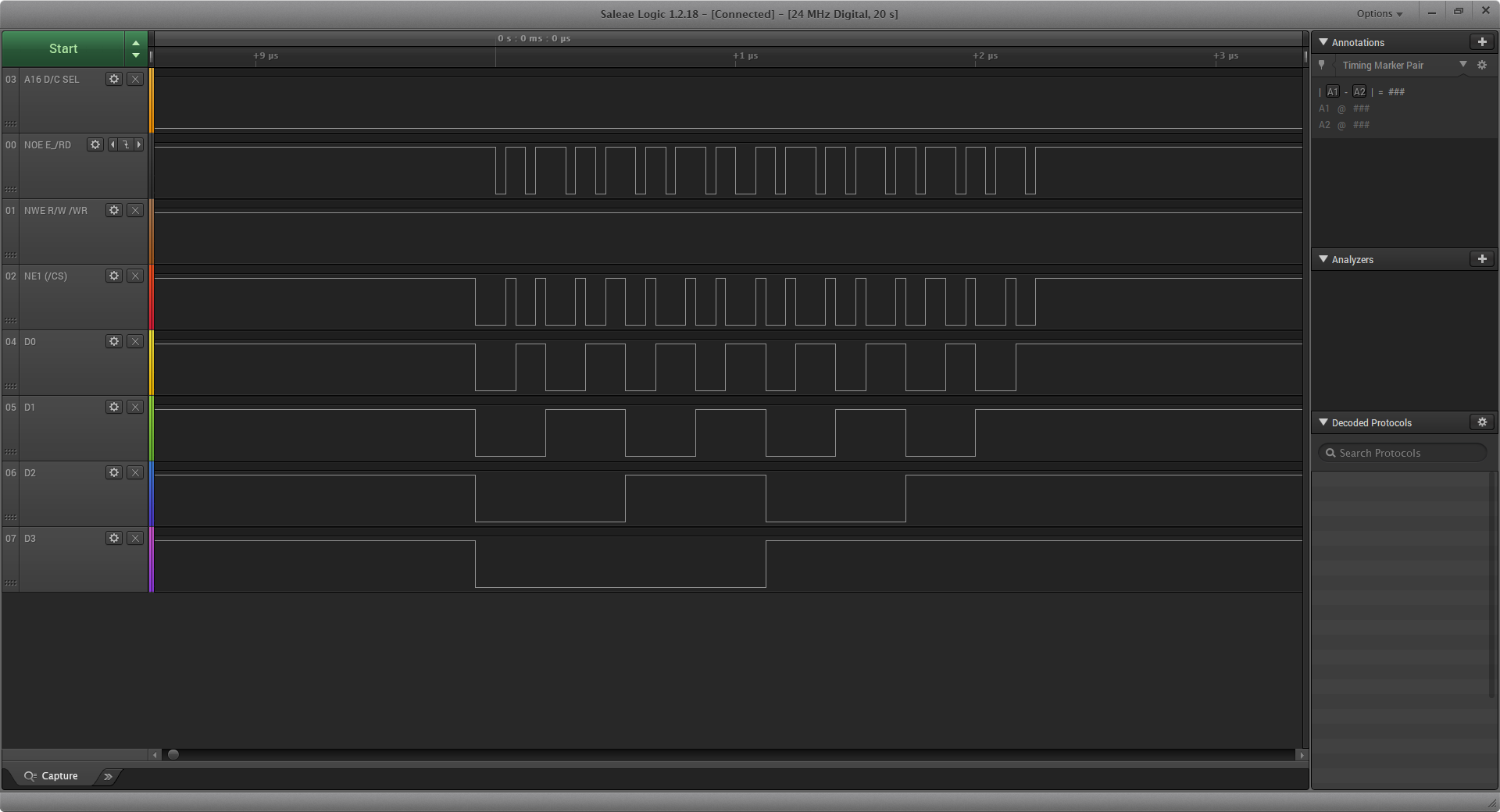
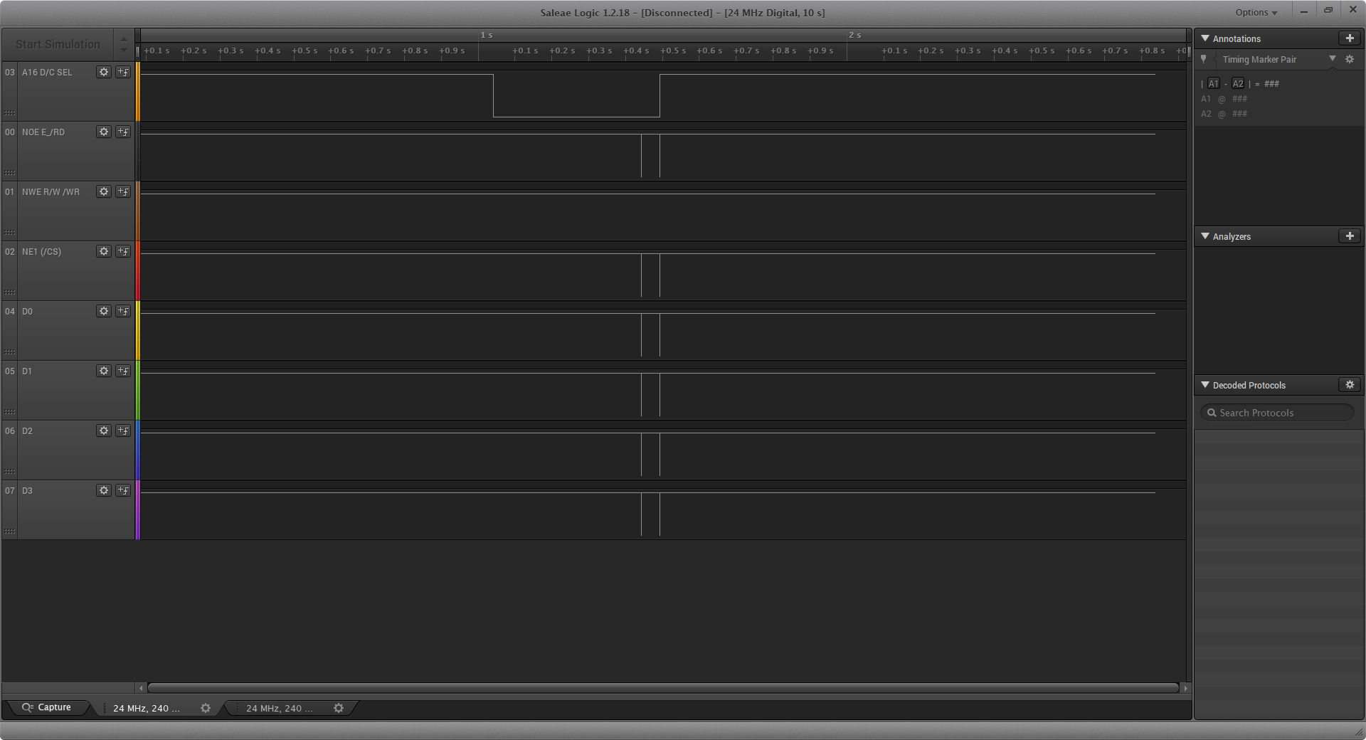
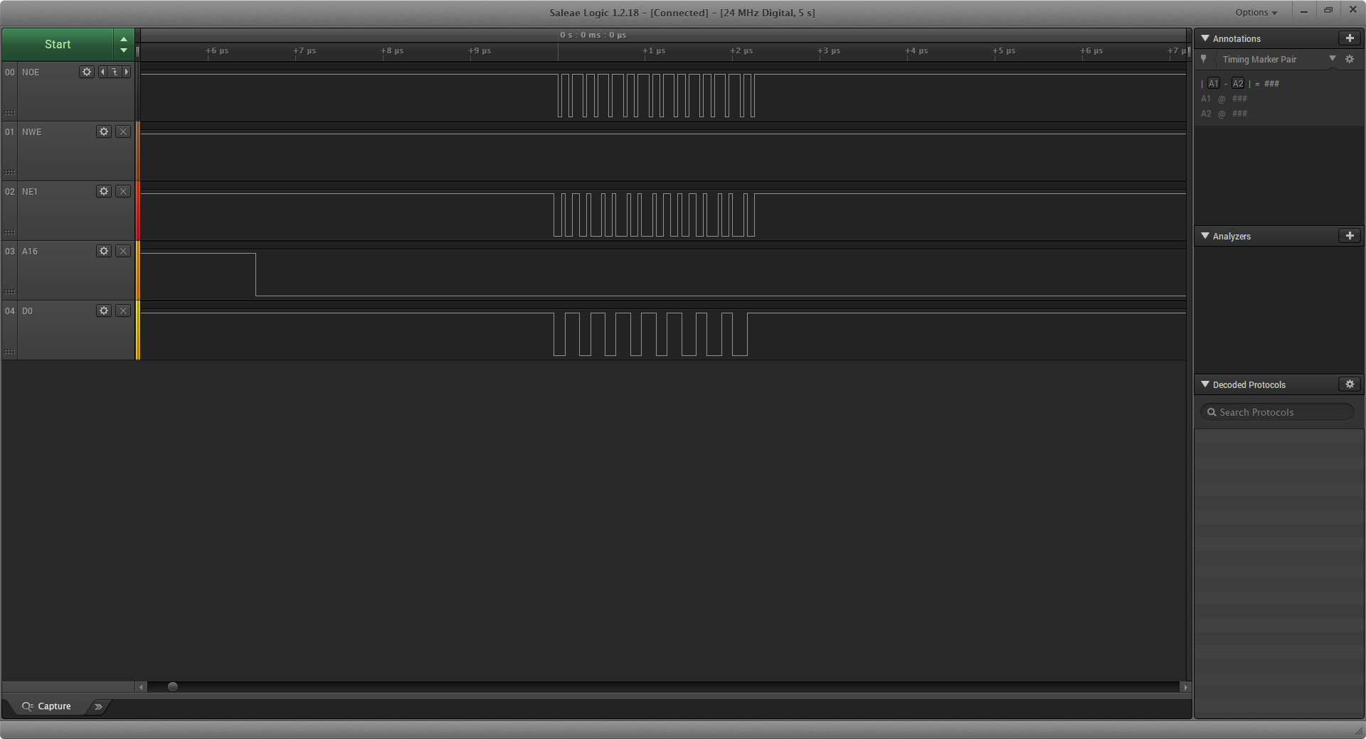
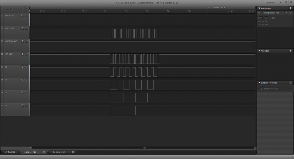
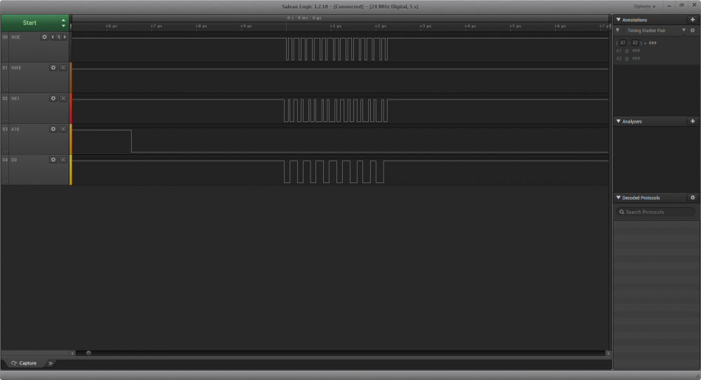
Ok, some updates... static void fmc_setup(void) { unsigned char FMC_Bank; rccEnableAHB3(RCC_AHB3ENR_FMCEN, 0); IOBus busD = {GPIOD, (1 << 0) | (1 << 1) | (1 << 4) | (1 << 5) | (1 << 7) | (1 << 8) | (1 << 9) | (1 << 10) | (1 << 11) | (1 << 14) | (1 << 15), 0}; IOBus busE = {GPIOE, (1 << 7) | (1 << 8) | (1 << 9) | (1 << 10) | (1 << 11) | (1 << 12) | (1 << 13) | (1 << 14) | (1 << 15), 0}; palSetBusMode(&busD, PAL_MODE_ALTERNATE(12)); palSetBusMode(&busE, PAL_MODE_ALTERNATE(12)); FMC_Bank = 0; FMC_Bank1->BTCR[FMC_Bank+1] = (FMC_BTR1_ADDSET_1 | FMC_BTR1_ADDSET_3) | \ (FMC_BTR1_DATAST_1 | FMC_BTR1_DATAST_3) | \ (FMC_BTR1_BUSTURN_1 | FMC_BTR1_BUSTURN_3); } int main(void) { halInit(); chSysInit(); fmc_setup(); volatile uint16_t* fmc = (uint16_t*)0x60000000; volatile uint16_t w[] = { 0xFFFF, 0x0000, 0xFFFF, 0x0000, 0xFFFF, 0x0000, 0xFFFF, 0x0000}; volatile uint8_t i = 0; volatile uint32_t j = 0; chThdSleepMilliseconds(500); while (true) { for(i = 0; i<8; i++) { fmc[j] = w[i]; j++; if(j == 0x6fffffff) j =0; } chThdSleepMilliseconds(2); } } Wired a Logic Analyzer to FMC pins and the code above give the expected (I think) output of many sequences as the image below. Next I moved to this code, ripped from the benchmark test: int main(void) { halInit(); chSysInit(); uint32_t i, pixels; coord_t height, width, rx, ry, rcx, rcy; volatile color_t random_color; chThdSleepMilliseconds(100); gfxInit(); gdispSetOrientation(GDISP_ROTATE_90); width = gdispGetWidth(); height = gdispGetHeight(); pixels = 0; for (i = 0; i < 5000; i++) { random_color = (rand() % 65535); rx = (rand() % (width-10)); ry = (rand() % (height-10)); rcx = (rand() % ((width-rx)-10))+10; rcy = (rand() % ((height-ry)-10))+10; gdispFillArea(rx, ry, rcx, rcy, random_color); pixels += (rcx+1)*(rcy+1); } while(TRUE) { chThdSleepMilliseconds(100); } } No matter what, on LA the code output appears to hang right after gfxInit(); This is the entire output, zoom maxed: And here in detail: Any thoughts on what could be the cause of the FMC output hanging after initialization? Thanks.

-
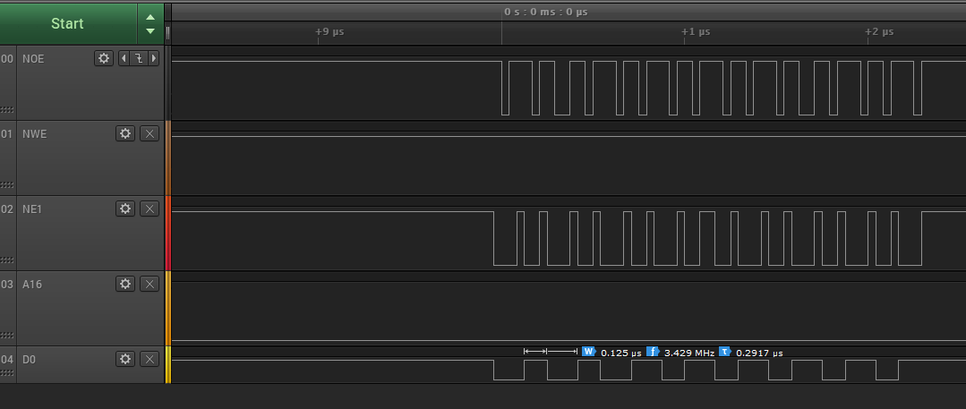
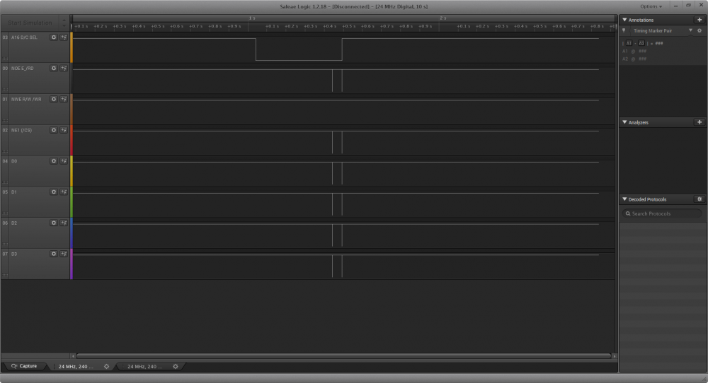
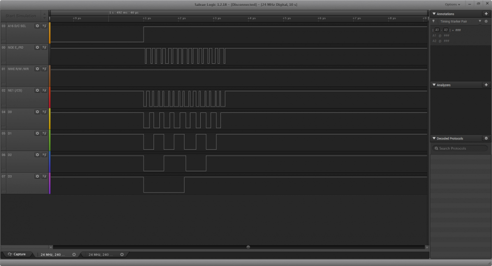
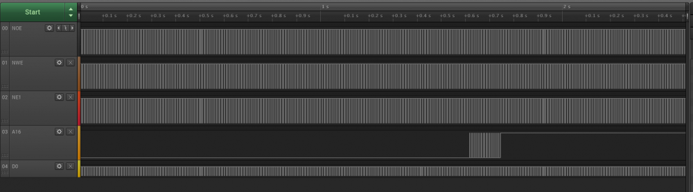
Hi Joel. Thanks. I've changed optimization level to 0 in makefile and FMC increasing from 0x60000000 to 0x6fffffff. Main thread sleep time was reduced to 2 ms as well. Ok, now we've got some things happening! Look like A16 goes low while we output some juicy data to sub bank1. And how it goes high when the address change to the next sub bank. I didn't understood that signal change sequence while going from low to high. Is it fine? What should be the next step? Figure out timings? What about 6800 and 8080 modes thing? Please, just give me a north to follow and I will try to sort things out. Thanks.
-
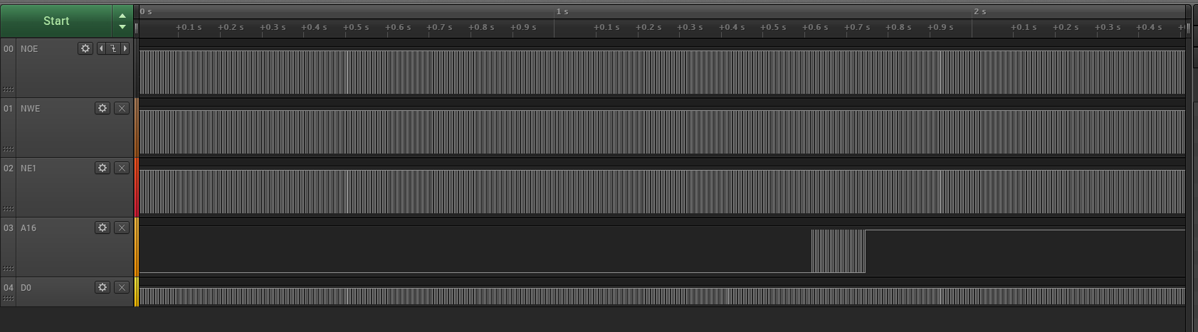
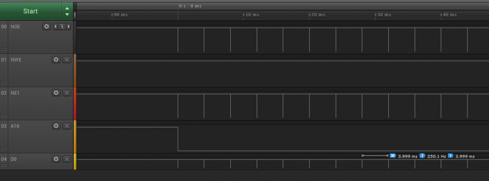
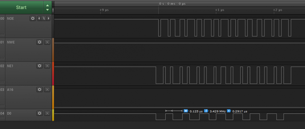
Ok, so following this board administrator advices I'm trying to isolate the problem. Started a project with nothing but FMC test code. I did it like this: #include "ch.h" #include "hal.h" //#include "gfx.h" static void fmc_setup(void) { unsigned char FMC_Bank; rccEnableAHB3(RCC_AHB3ENR_FMCEN, 0); IOBus busD = {GPIOD, (1 << 0) | (1 << 1) | (1 << 4) | (1 << 5) | (1 << 7) | (1 << 8) | (1 << 9) | (1 << 10) | (1 << 11) | (1 << 14) | (1 << 15), 0}; IOBus busE = {GPIOE, (1 << 7) | (1 << 8) | (1 << 9) | (1 << 10) | (1 << 11) | (1 << 12) | (1 << 13) | (1 << 14) | (1 << 15), 0}; palSetBusMode(&busD, PAL_MODE_ALTERNATE(12)); palSetBusMode(&busE, PAL_MODE_ALTERNATE(12)); FMC_Bank = 0; FMC_Bank1->BTCR[FMC_Bank+1] = (FMC_BTR1_ADDSET_1 | FMC_BTR1_ADDSET_3) | \ (FMC_BTR1_DATAST_1 | FMC_BTR1_DATAST_3) | \ (FMC_BTR1_BUSTURN_1 | FMC_BTR1_BUSTURN_3); } int main(void) { halInit(); chSysInit(); fmc_setup(); volatile uint16_t* fmc = (uint16_t*)0x60000000; volatile uint16_t w[] = { 0xFFFF, 0x0000, 0xFFFF, 0x0000, 0xFFFF, 0x0000, 0xFFFF, 0x0000}; volatile uint8_t i = 0; while (true) { for(i = 0; i<8; i++) { fmc[0] = w[i]; } chThdSleepMilliseconds(50); } } And attached here is a capture from LA. I don't know why but it should be constantly streaming to FMC bus, instead the captured data are just those on the picture.
-
Joel, thanks for helping and I'm sorry for taking your time. I now you are a very busy person and I really appreciate your attention. Knowing this, now I see the value 0x60020000 is wrong for FSMC_A16 since it would be a 1 on the 18th bit address bit 17. It should be 0x60010000. Unless I missed something, all the pins are correctly set, including Register Select which is PD11. I will triple-check this. I will do all the recommended tests using a scope and check timings in display datasheet, as suggested. I still have two things that I didn't get. 1) Looking at the struct from example board file above, it's missing 3 things. Mode, flipHorz and flipVert. Flip are pretty straight forward, but for mode I have all those options and I'm kind of lost on which should I be using. static const LCD_Parameters DisplayTimings[] = { // You need one of these array elements per display { 800, 480, // Panel width and height 2, 2, 41, // Horizontal Timings (back porch, front porch, pulse) CALC_PERIOD(800,2,2,41), // Total Horizontal Period (calculated from above line) 2, 2, 10, // Vertical Timings (back porch, front porch, pulse) CALC_PERIOD(480,2,2,10), // Total Vertical Period (calculated from above line) CALC_FPR(800,480,2,2,41,2,2,10,60ULL) // FPR - the 60ULL is the frames per second. Note the ULL! }, }; /* Set the pannel data width */ #define LCD_PANEL_DATA_WIDTH_24BIT (1<<5) // 18bit default /* Set the color deeph enhancement */ #define LCD_PANEL_ENABLE_FRC ((1<<3) | (1<<4)) #define LCD_PANEL_ENABLE_DITHERING (1<<4) // no enhancement default /* Set the dot clock pulse polarity */ #define LCD_PANEL_LSHIFT_FALLING_EDGE (1<<2) // default rising edge /* Set the horizontal sync pulse polarity */ #define LCD_PANEL_LLINE_ACTIVE_HIGH (1<<1) // default active low /* Set the vertical sync pulse polarity */ #define LCD_PANEL_LFRAME_ACTIVE_HIGH (1<0) // default active low /* Set the lcd panel mode */ #define LCD_PANEL_MODE_TTL ((1<<7) << 8) // default mode is Hsync+Vsync +DE /* Set the lcd panel interface type */ // default TFT mode #define LCD_PANEL_TYPE_SERIAL_RGB_MODE ((1<<6) << 8) // Serial RGB mode #define LCD_PANEL_TYPE_SERIAL_RGB_DUMMY_MODE (((1<<5) | (1<<6)) << 8) // Serial RGB+dummy mode 2) My display come from factory in 8080 parallel mode. I have no idea if the driver is expecting this or Motorola 6800. I don't even where it should be set. Would be it a STM32 FMC setting? Or it's implicit in the driver code? Maybe one of the previously mentioned mode macros? I also see an option for 24bit width, shouldn't it be a 16-bit option? Thank you very much. Any progress will be written here.
-
H! I've been trying to make this work without success so if anyone could help me I would be very glad. I'm trying to get this display working with my STM32F746ZG based nucleo144 board. Display is 800x480px 7" drived by SSD1963 in 16-bit 8080 parallel mode. I have Register Select at A16/PD11. I don't know if the selected mode is wrong and how to change it or fi I have the FMC peripheral initialized properly. Anyone could please explain these lines to me? I can see from where 0x60000000 come from, but what about 0x60020000? #define GDISP_REG (*((volatile uint16_t *) 0x60000000)) /* RS = 0 */ #define GDISP_RAM (*((volatile uint16_t *) 0x60020000)) /* RS = 1 */ Attached is an image showing what happens. Basically, there is no image on display, only vertical lines in a white backgroud. My board file: /* * This file is subject to the terms of the GFX License. If a copy of * the license was not distributed with this file, you can obtain one at: * * http://chibios-gfx.com/license.html */ /** * @file boards/addons/gdisp/board_SSD1963_fsmc.h * @brief GDISP Graphic Driver subsystem board interface for the SSD1963 display. * * @note This file contains a mix of hardware specific and operating system specific * code. You will need to change it for your CPU and/or operating system. */ #ifndef _GDISP_LLD_BOARD_H #define _GDISP_LLD_BOARD_H static const LCD_Parameters DisplayTimings[] = { // You need one of these array elements per display { 800, 480, // Panel width and height 2, 2, 41, // Horizontal Timings (back porch, front porch, pulse) CALC_PERIOD(800,2,2,41), // Total Horizontal Period (calculated from above line) 2, 2, 10, // Vertical Timings (back porch, front porch, pulse) CALC_PERIOD(480,2,2,10), // Total Vertical Period (calculated from above line) CALC_FPR(800,480,2,2,41,2,2,10,60ULL) // FPR - the 60ULL is the frames per second. Note the ULL! }, }; // For a multiple display configuration we would put all this in a structure and then // set g->board to that structure. /* Using FSMC A16 as RS */ #define GDISP_REG (*((volatile uint16_t *) 0x60000000)) /* RS = 0 */ #define GDISP_RAM (*((volatile uint16_t *) 0x60020000)) /* RS = 1 */ static GFXINLINE void init_board(GDisplay *g) { // As we are not using multiple displays we set g->board to NULL as we don't use it. g->board = 0; switch(g->controllerdisplay) { case 0: // Set up for Display 0 #if defined(STM32F1XX) || defined(STM32F3XX) /* FSMC setup for F1/F3 */ rccEnableAHB(RCC_AHBENR_FSMCEN, 0); #elif defined(STM32F4XX) || defined(STM32F2XX) /* STM32F2-F4 FSMC init */ rccEnableAHB3(RCC_AHB3ENR_FSMCEN, 0); #elif defined(STM32F7XX) rccEnableAHB3(RCC_AHB3ENR_FMCEN, 0); #else #error "FSMC not implemented for this device" #endif /* set pins to FSMC mode */ IOBus busD = {GPIOD, (1 << 0) | (1 << 1) | (1 << 4) | (1 << 5) | (1 << 7) | (1 << 8) | (1 << 9) | (1 << 10) | (1 << 11) | (1 << 14) | (1 << 15), 0}; IOBus busE = {GPIOE, (1 << 7) | (1 << 8) | (1 << 9) | (1 << 10) | (1 << 11) | (1 << 12) | (1 << 13) | (1 << 14) | (1 << 15), 0}; palSetBusMode(&busD, PAL_MODE_ALTERNATE(12)); palSetBusMode(&busE, PAL_MODE_ALTERNATE(12)); /* FSMC timing */ FMC_Bank1->BTCR[0+1] = (FMC_BTR1_ADDSET_1 | FMC_BTR1_ADDSET_3) \ | (FMC_BTR1_DATAST_1 | FMC_BTR1_DATAST_3) \ | (FMC_BTR1_BUSTURN_1 | FMC_BTR1_BUSTURN_3) ; /* FSMC_Bank1->BTCR[0+1] = (FSMC_BTR1_ADDSET_1 | FSMC_BTR1_ADDSET_3) \ | (FSMC_BTR1_DATAST_1 | FSMC_BTR1_DATAST_3) \ | (FSMC_BTR1_BUSTURN_1 | FSMC_BTR1_BUSTURN_3) ; */ /* Bank1 NOR/SRAM control register configuration * This is actually not needed as already set by default after reset */ //FSMC_Bank1->BTCR[0] = FSMC_BCR1_MWID_0 | FSMC_BCR1_WREN | FSMC_BCR1_MBKEN; break; } } static GFXINLINE void post_init_board(GDisplay *g) { (void) g; /* FSMC delay reduced as the controller now runs at full speed */ FMC_Bank1->BTCR[0+1] = FMC_BTR1_ADDSET_0 | FMC_BTR1_DATAST_2 | FMC_BTR1_BUSTURN_0 ; FMC_Bank1->BTCR[0] = FMC_BCR1_MWID_0 | FMC_BCR1_WREN | FMC_BCR1_MBKEN; //FSMC_Bank1->BTCR[0+1] = FSMC_BTR1_ADDSET_0 | FSMC_BTR1_DATAST_2 | FSMC_BTR1_BUSTURN_0 ; //FSMC_Bank1->BTCR[0] = FSMC_BCR1_MWID_0 | FSMC_BCR1_WREN | FSMC_BCR1_MBKEN; } static GFXINLINE void setpin_reset(GDisplay *g, bool_t state) { (void) g; (void) state; } static GFXINLINE void acquire_bus(GDisplay *g) { (void) g; } static GFXINLINE void release_bus(GDisplay *g) { (void) g; } static GFXINLINE void write_index(GDisplay *g, uint16_t index) { (void) g; GDISP_REG = index; } static GFXINLINE void write_data(GDisplay *g, uint16_t data) { (void) g; GDISP_RAM = data; } #endif /* _GDISP_LLD_BOARD_H */ Thanks in advance.
-
Guys, thanks for all clarifications. I will take all the information in account, probably going with an F7 and RA8875.
-
Hi cpu20! Thanks for your reply. I've been doing my homework in the past few days. With my current setup I can't even display gifs and pngs. Looking into the drivers, SSD ones appears to already have hardware acceleration implemented. RA8875 have more hardware acceleration options but almost none of them are present on driver. I don't know how easy would be to a newbie guy like me implement those functions. I will take a look on how it was done on another driver. The MCU I was planning to use was an STM32F4 with192 kB ram and 1 MB flash. For image storage, is possible to hook another device to fsmc bus? Thank you.
-
Hi! I'm basically an AVR 8-bit withou much experience with real time OSes. Recently I've been learning ChibiOS and STM32 microcontrollers. Using uGFX I was able to properly drive an small and very slow 2.2" ILI9341 SPI display. I want to buy a bigger and faster display for use in a future project. I will probably pick an FSMC capable STM32, unless someone say LTDC would be a better option. Actually I have considered these options: 9 in 1) 9 inch LCD Module TFT Display w/OPTL Touch Panel,I2C+Serial SPI 2) 9"TFT LCD Module Touch Display w/SSD1963 Controller Board for Arduino 10.1 in 3) Serial SPI I2C 10.1"TFT LCD Module Dislay w/RA8876,OPTL Touch Panel Between 1 and 2 (RA8875 and SSD1963) which one would be faster and better supported by uGFX considering they would be wired to 16-bit FSMC interface? By the controllers datasheet RA8875 apparently have more hardware acceleration options. Option 3 seens to be slightly different from RA8875. How difficult would be to get it working with uGFX and what are the benefits (beside increased screen size and resolution)? If you have any other suggestion, I would be glad to hear it! Thanks in advance!
-
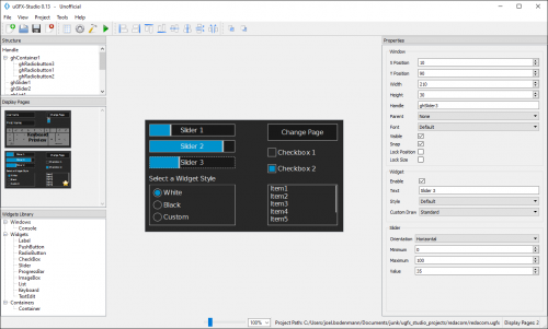 µGFX-Studio allows fast and intuitive GUI design for your application. Even it's in early development phase it's beign constantly improved and is very usable on latest version (0.13). Using this very handy tool to design your GUI is easy and will allow the generated code to be used in your project in just a few clicks.
 -
 This library is state-of-the-art software provinding an easy and fast way to integrate graphic displays to your project. It also provides additional drivers for touchscreens devices. Audio input/output modules are included too. Support is great, through community forum and IRC channel. It's free to use for home and hobby applications and commercial licenses have a great price. uGFX supports the more popular boards, display drivers and operational systems or just bare metal applications. I would recommend this to anyone who needs a high modular and lightweight solution.
 -
What it means? No source available for "Reset_Handler() "