nquantum
-
Posts
32 -
Joined
-
Last visited
Content Type
Forums
Store
Downloads
Blogs
Everything posted by nquantum
-
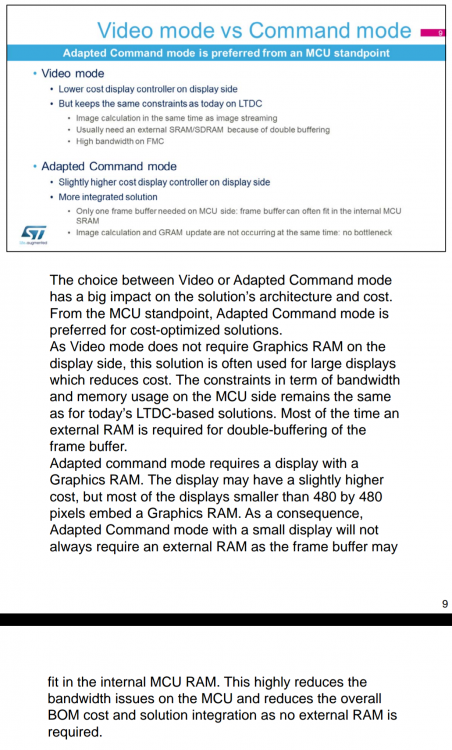
I'm improving old board files I've done before. Before it depend on BSD driver and font from ST example project. Since that is too much and not necessary for normally. I changed it to use with code from CubeMX and dependence free from BSD driver and fonts. I would like to ask. 1. I've check LTDC driver in ugfx is Point and Block Model correct? And the require is : gdisp_lld_init() , gdisp_lld_draw_pixel() It seem define in gdisp_lld_config.h which will use: GDISP_HARDWARE_DRAWPIXEL for gdisp_lld_draw_pixel() GDISP_HARDWARE_FILLS for gdisp_lld_fill_area() GDISP_HARDWARE_BITFILLS for gdisp_lld_blit_area() From what I understand is DMA2D is use in gdisp_lld_fill_area() and gdisp_lld_blit_area() but not in gdisp_lld_draw_pixel() am I correct? It seem that if I comment out DMA2D not use them only gdisp_lld_draw_pixel() is working already. But I'm not sure there is some where in call use DMA2D when gdisp_lld_draw_pixel() is called or not? I ask because I will change some code that use DMA2D setting come from CubeMX for easy understand and adjust. So when use next project all setting LTDC, DSI, DMA2D, FMC, RCC and Clock will generate from CubeMX and only board file/driver then link with those. Is gdisp_lld_draw_pixel() involved in convert color pixel that use benefit of DMA2D or not? 2. It seem like old of my board file and the current one that upload to repository is use Adapt command mode. There is also Video mode to choose. Which is should better in term of smooth transition picture. But I'm not have much experience on this. It seem like Adapt command mode use frame buffer to refresh display. If use Video mode should be better? I think you have more experience can you please explain use case or benefit of this two mode? Command mode vs Video mode. Thank
-
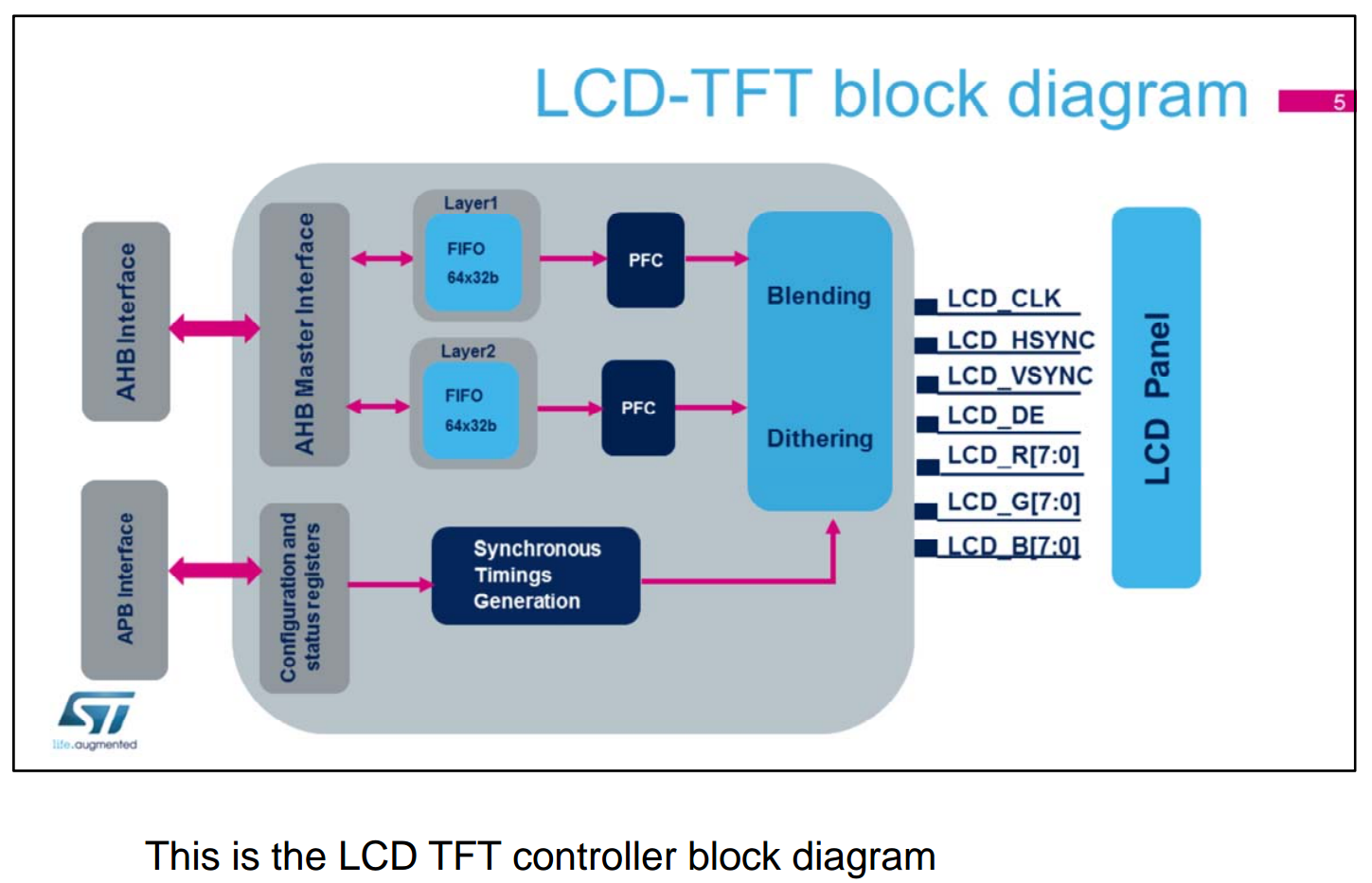
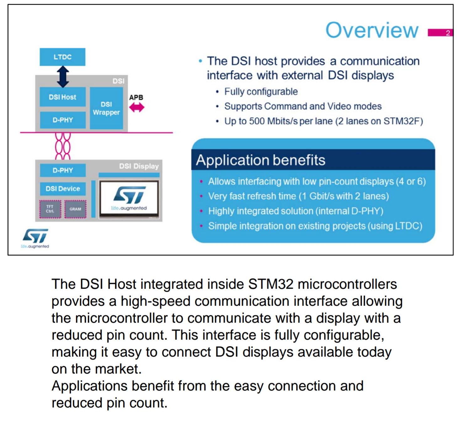
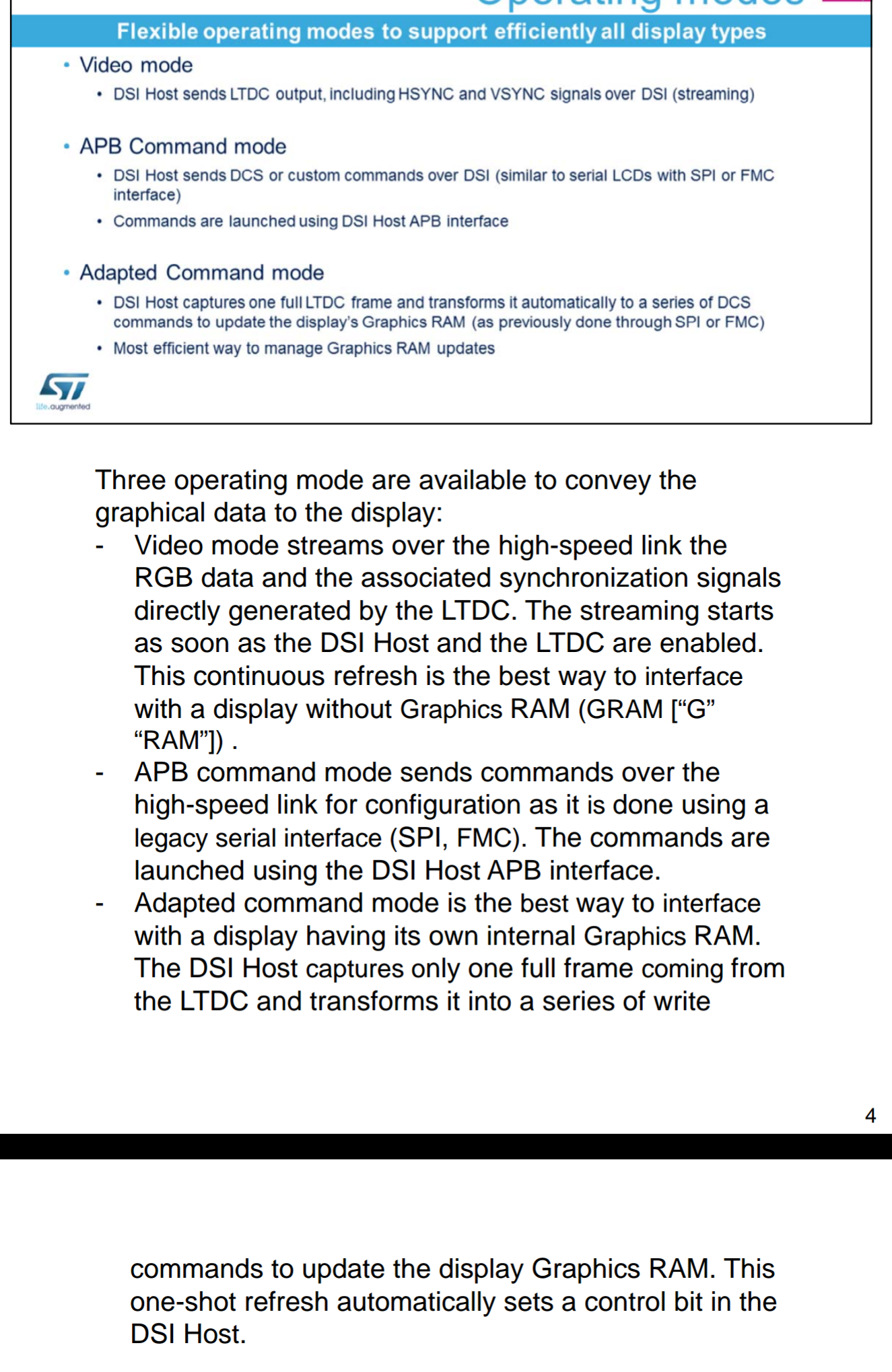
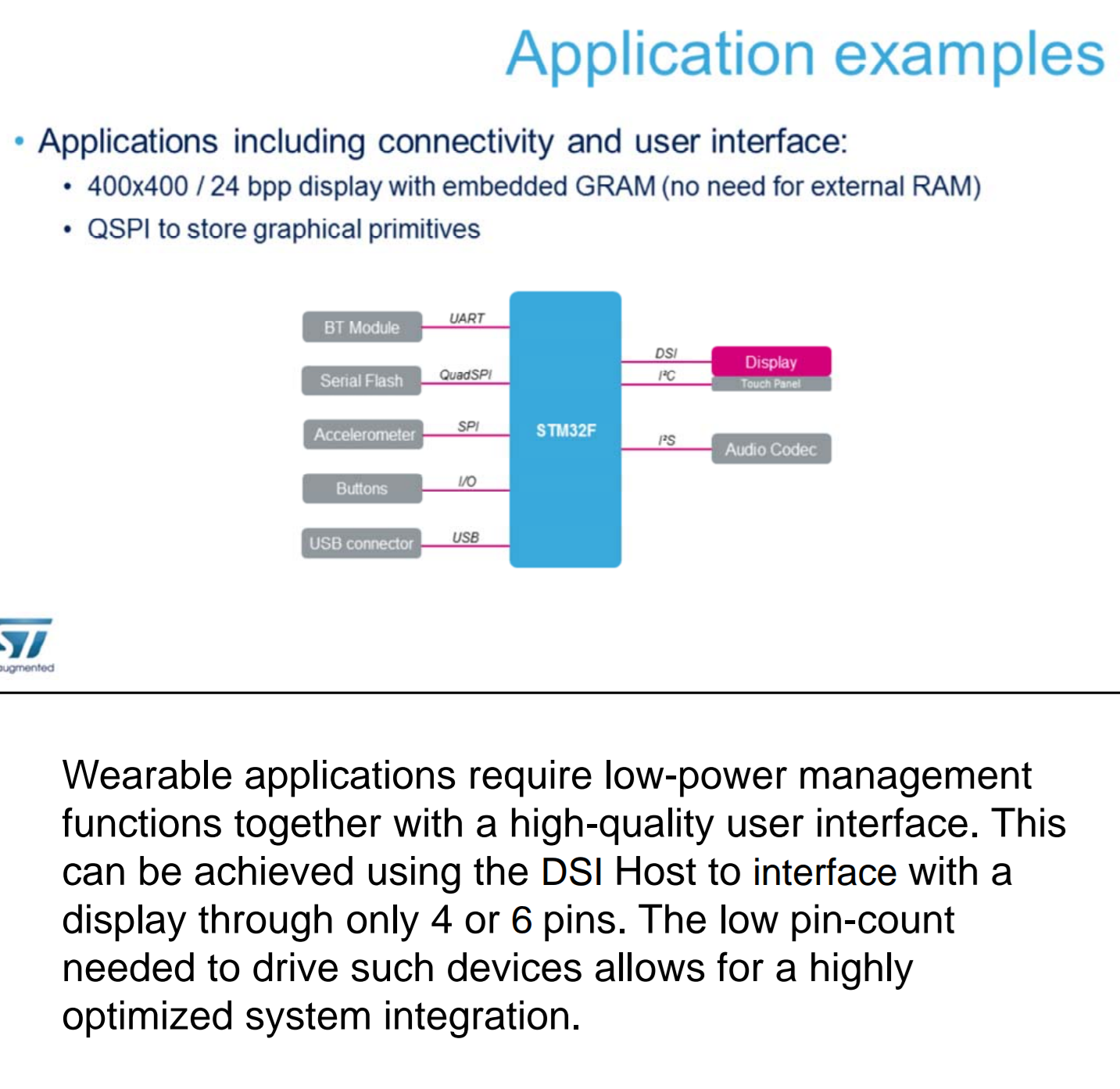
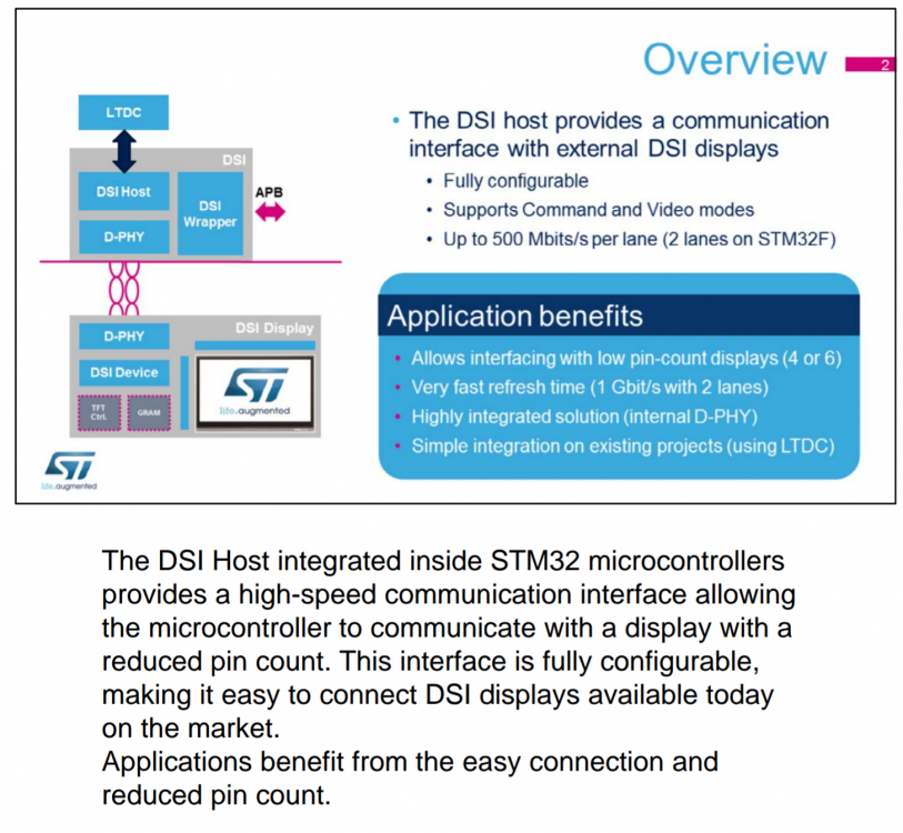
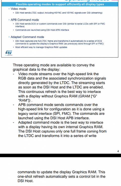
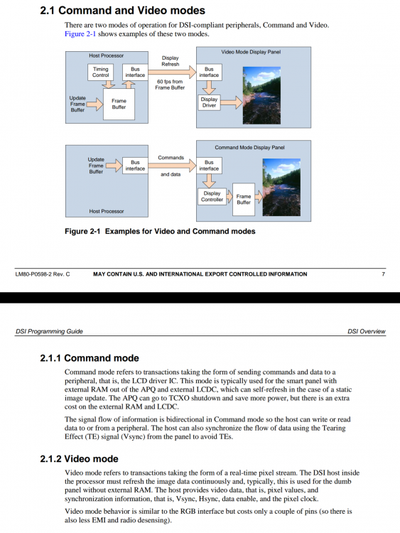
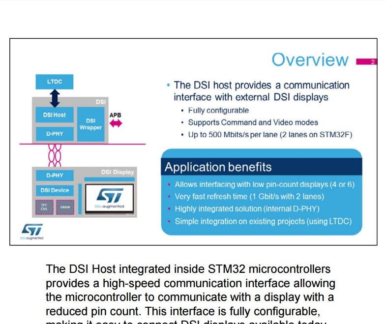
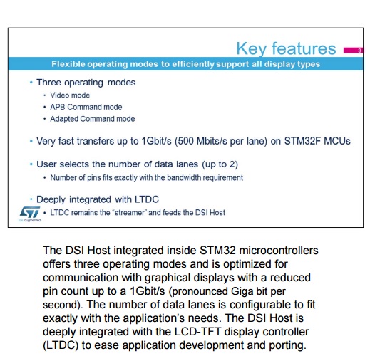
Yes that correct I write to buffer and LTDC use its AHB and FIFO stuff trough FMC/QUADSPI interface to take care of update screen. Then LTDC automatic send to DSI HOST stream to panel trough serial bus. But smooth or not so sure. I should lag for some I think since it trough 2process, LTDC and DSI HOST. Since I only experiment with still picture only. Never try animation yet. Normally microcontrollers they direct use their I/O to interface with TFT/LCD? They have no LTDC? I never experience other TFT before only basic character LCD in those 8bit micro. This is my first TFT panel with 32bit micro. (very happy already to start to see 1st picture in TFT myself ) You quite correct. I also attach pictures for reference. For video mode LTDC generate sync signals to DSI HOST then DSI stream serial to panel. For command mode send command and data to update GRAM of panel then panel controller take care of update panel. Qualcomm datasheet give info quite clear. (ST make me so headache) The DSI is a specification by the MIPI and is targeted at reducing the cost of the display subsystem in mobile and embedded-computing devices. It defines a serial bus and communication protocol between the host and the device (client). The bus includes one high-speed clock lane and one or more data lanes. Each lane is carried on tow wires and uses low voltage, differential signaling. So I think that why they do care on price than performance. By reduce pin count can reduce complex of system also cost. I think it just like parallel port change to serial port that it. And for command mode they do need panel to manage more thing: GRAM, controller. Instead video mode so that it can use dumb display only to display streaming.


-
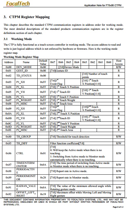
Update driver files after I see: https://community.ugfx.io/topic/413-ft6x06-driver/ STM32F469 Discovery use FT6206. The compatible of FT5x06 and FT6x06 I read from this topic let me check datasheet of both. There is difference FT5x06 can have touch point up to 10 but FT6x06 only 2. Also little bit difference in register. Some doesn't exist (according to datasheet) in FT6x06. So I update the define value. However after test with demos/tools/touch_driver_test I found out that some of those don't exist register and compensate setting from FT5x06 do have positive effect. So I keep those compensate setting and give comment information in to file and also adjust some register. Also found out that the precise touch of manual crosshair calibration effect whether I can touch near the edge of screen or not. According from drawing page. The more precise touch I do also proper GMOUSE_FT6x06_FINGER_CALIBRATE_ERROR and GMOUSE_FT6x06_PEN_CALIBRATE_ERROR value do effect the precise of touch result and near edge of screen touch. Drawing page let me verify those calibration. And I can see manual calibration does better job than auto calibration. The precision is better. ft6x06.h gmouse_lld_FT6x06.c gmouse_lld_FT6x06_board.h
-
I've finish let try these files. Thank for Maytham this is base from him. Thank for suggest of Joel Bodenmann and inmarket for detail information. Driver depends on ST HAL , Component , BSP also I take auto-calibrate function from FT6x06 driver supply by ST. Take a look and please comment/review. Also still curious to know this. For benchmark tools I got 123,227,408 Pixels/s. It not a refresh rate. How can I measure refresh rate? Or 123,227,408/(800x480) ? ft6x06.h gmouse_lld_FT6x06.c gmouse_lld_FT6x06_board.h
-
For benchmark tools I got 123,227,408 Pixels/s. It not a refresh rate. How can I measure refresh rate? Or 123,227,408/(800x480) ?
-
I found info in CMSIS I will try replace: DWT_CYCCNT to DWT->CYCCNT DWT_CTRL to DWT_CTRL Then compile no error. I haven't bring ST board now. Will try test result tonight.
-
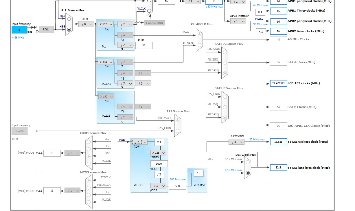
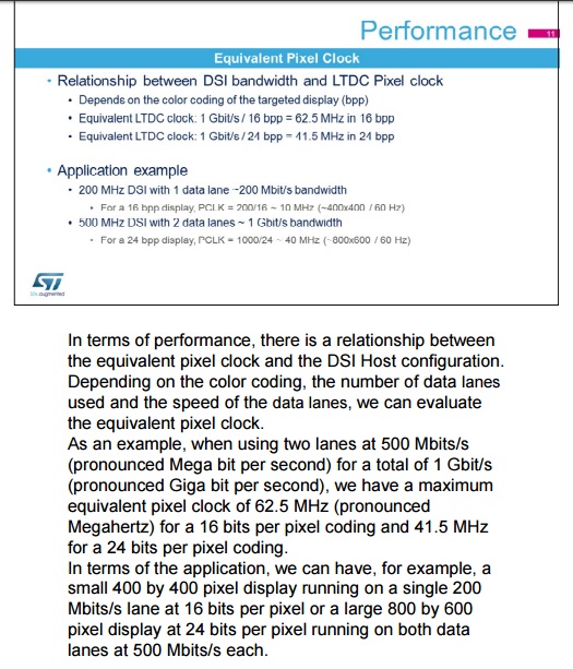
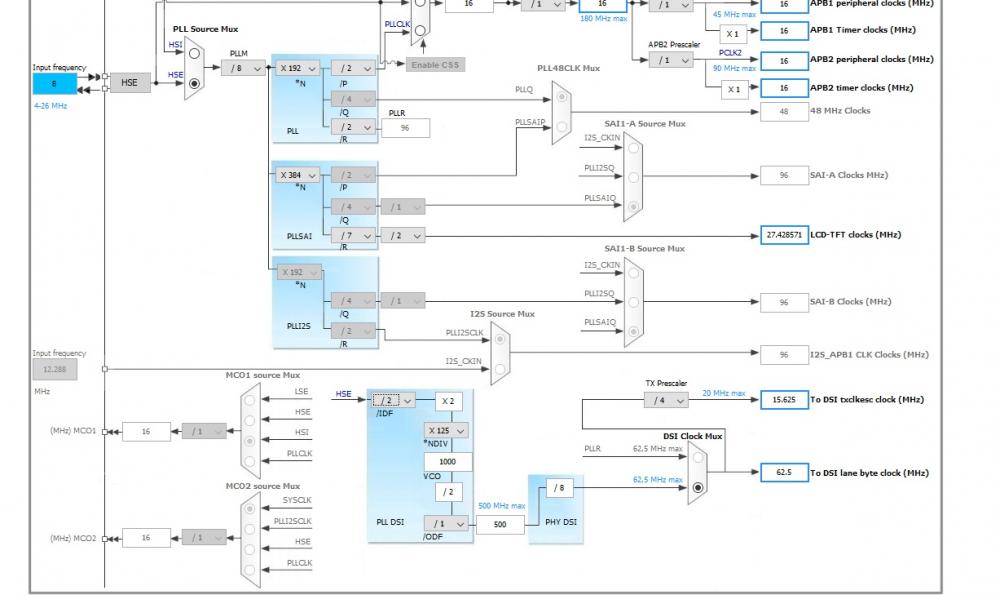
That a good question! I should ask myself. After think a lot don't know how to measure it! I search from forum If refresh rate come from initial code in driver then. - DSI HOST upto 500Mbits/lane > I use 2 lanes. > 1Gbits total - I use RGB888 so 24bpp - LTDC clock is 27.429MHz So for DSI HOST 1Gbist/800x480pixelsx24bpp = 108Hz , And for LTDC 27.429M/800x480=71.429Hz >> So if not wrong calculate I should get >60Hz. I think. Is there a way to verify this? In case of demo/benchmarks I get error on 'DWT_CYCCNT' undeclared (first use in this function) 'DWT_CTRL' undeclared (first use in this function) Thank you, inmarket. I can see the output onscreen solid and good. That clearly ugfx manage well. However I do record clips vdo to more clearly explain. So that you can see if this is normal or not. And you can see in the begining the 2048 value... clip1 clip2 Please take a look and suggest/comment.
-
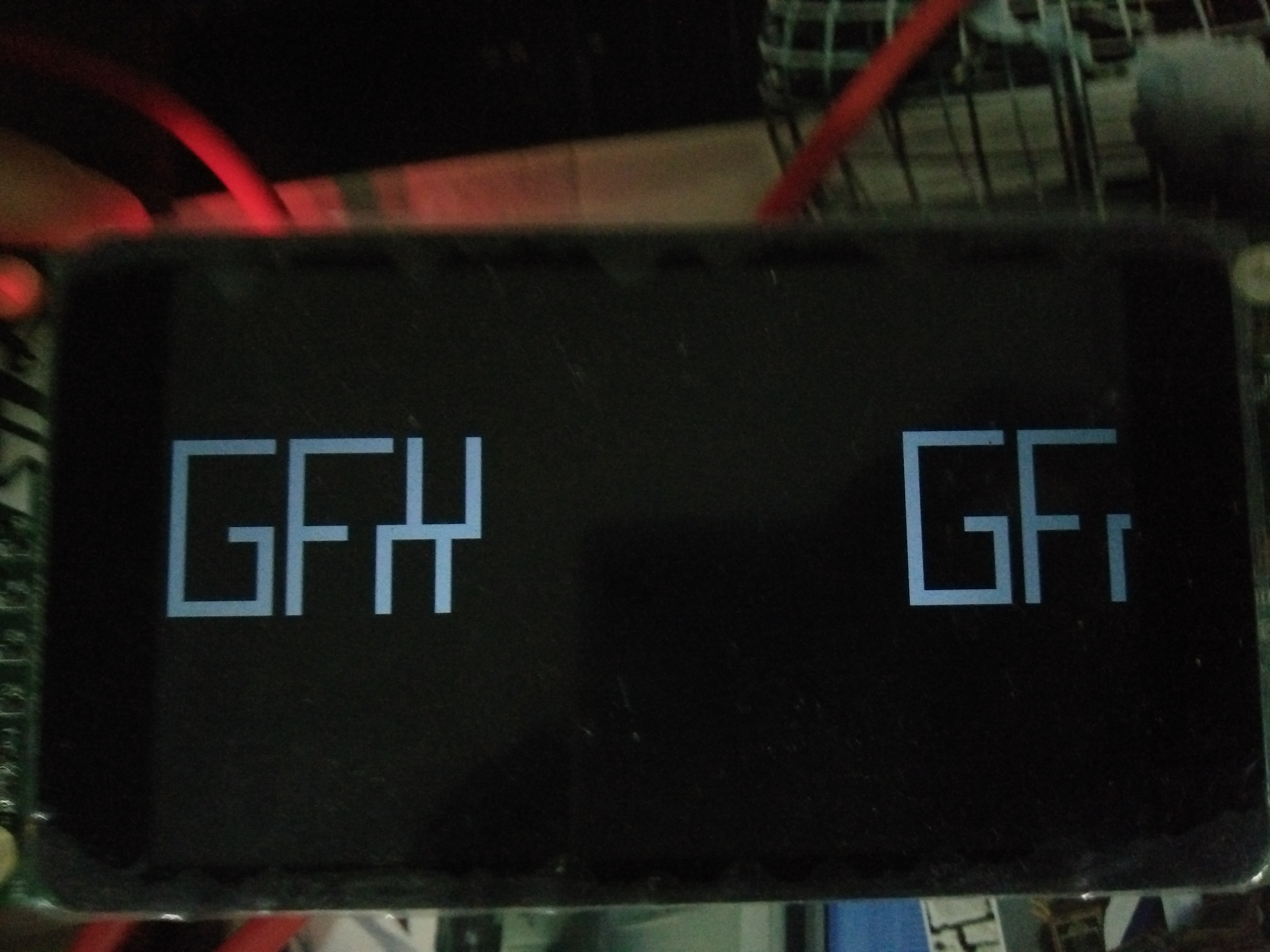
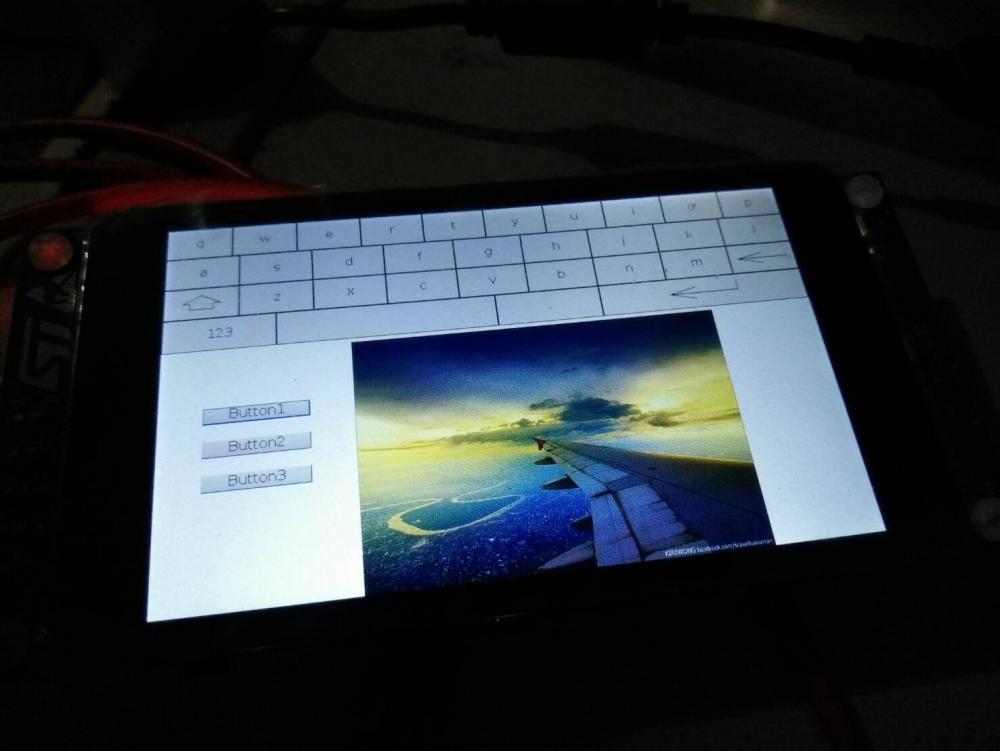
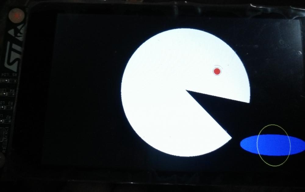
Take a break: A pic with create from uGFX Studio. Look nice :-) No action code for touch-button event yet (still learning) :-)
-
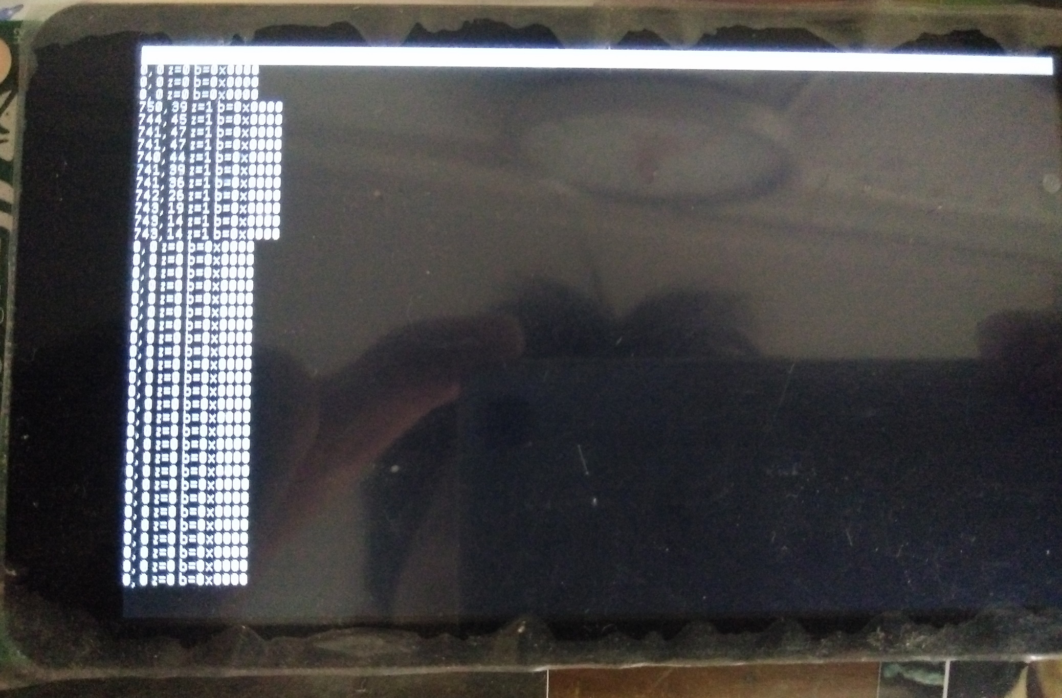
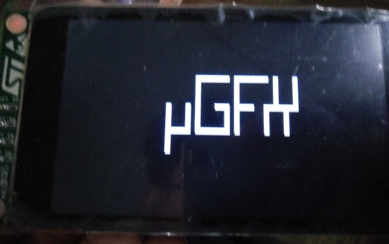
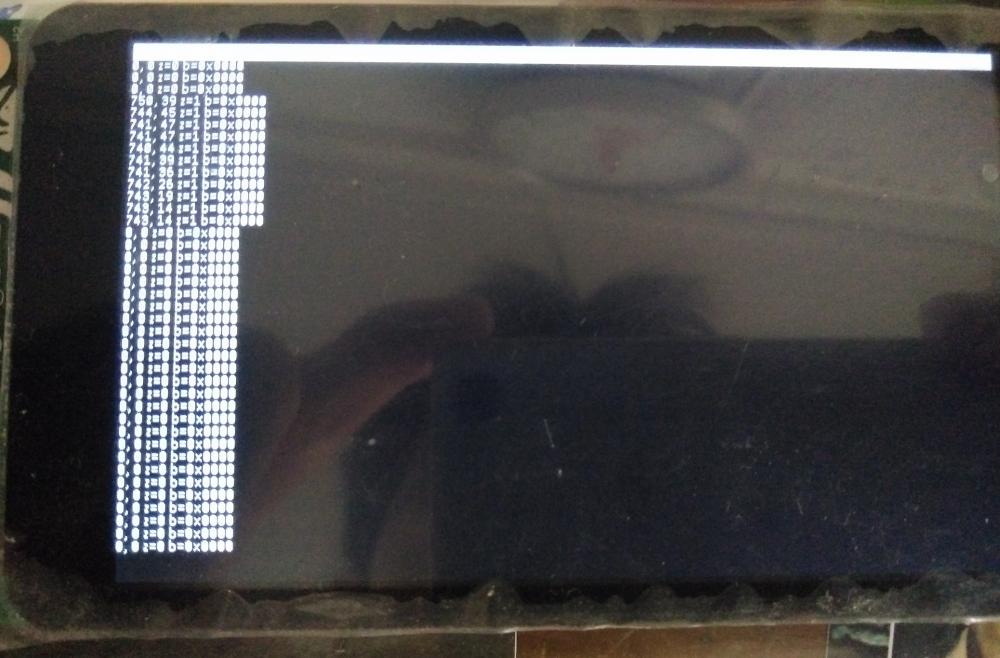
Okay thank Now I see that PEN/FINGER. Been busy these days. Now I can use auto-calibrate from ST FT6x06 without problem. Have to say there is hard to find detail in datasheet even hard to find data sheet/application note. Only get little strange: test demos/tools/touch_raw_readings they seem to skip calibration 4-spot touch when power on unlike others demos but that okay. The initial display after uGFX screen show x = 2048, y = 0, z = 1 meaning MSB 12th bit in x is set. Just like someone touch. But there isn't. Once I press any place then it show number of place as normal for example x = 125 ,y = 111 ,z = 1 and back to x = 0, y = 0, z = 0 then no touch. Every time like this so not random issue. Still find what cause this. From what I test I seem like nature of controller since position reading work as normal, also writing. Still look into it more. Do u think of anything?
-
I think I get it the reason to call read_word , another function than read_byte coz this will take care of the coordination.
-
I have some question. Okay GMOUSE_FT6x06_PEN_CALIBRATE_ERROR, GMOUSE_FT6x06_FINGER_CALIBRATE_ERROR 1. I've increase GMOUSE_FT6x06_PEN_CALIBRATE_ERROR value when I use finger in touch calibration now it pass. But try with GMOUSE_FT6x06_FINGER_CALIBRATE_ERROR is not. So question is how ugfx know I use finger or pen? In GINPUT? In what file/function it make decision? I try to find but not found. Or it is decide in board driver file? 2. In driver GINPUT I've check detail about read x,y,z is it okay to only XH, YH register? No need XL, YL? /* Get the X, Y, Z values */ pdr->x = (coord_t)(read_word(m, FT6x06_TOUCH1_XH) & 0x0fff); pdr->y = (coord_t)read_word(m, FT6x06_TOUCH1_YH); pdr->z = 1; Even it work well but I see in datasheet there is XH,YH for 4MSB bit and XL,YL for 8LSB bit. No need to get that value? Or it is enough already to get only XH,YH register? And yet also FT5x06, FT6x06, FT5336 in ugfx/drivers/ginput/touch seem to be like this also (read from XH,YH). Also in XH bit 7-4 is for other thing not position also YH bit7-4. There no need to mask those and ugfx can understand? Yes driver I test it almost work well now only I check for detail and check in the auto-calibration but these question are still in my curiosity.
-
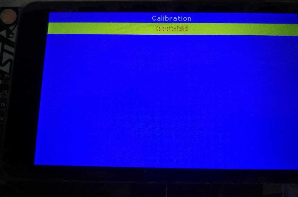
Thread solved! Thank you for your real detail. (how can you spot problem so quick!?) I try sourcetree and master repository already. Great even it not solve this problem. However set the GFX_CPU to GFX_CPU_CORTEX_M4_FP in gfxconfig.h does solve problem. Now thread working. Then I go back and try GINPUT again and it work now! Wow! I not yet touch GFX_COMPILER but it seem to work well now. gmouse_lld_FT6x06_board.h Come with self-calibration #define GMOUSE_FT6x06_SELF_CALIBRATE FALSE//TRUE when it set to true. Out put from demos/tools/touch_raw_reading resolution is limited 644-798 / 0-58 but once I set self-calibration to false then it seem to be 800 / 480 same as display. I will check into detail. Also when self-calibration is false , calibration display-page is apear after power-on/ugfx logo. Only it calibration failed every time I do calibrate even slow/long press touch. I going to see it.
-
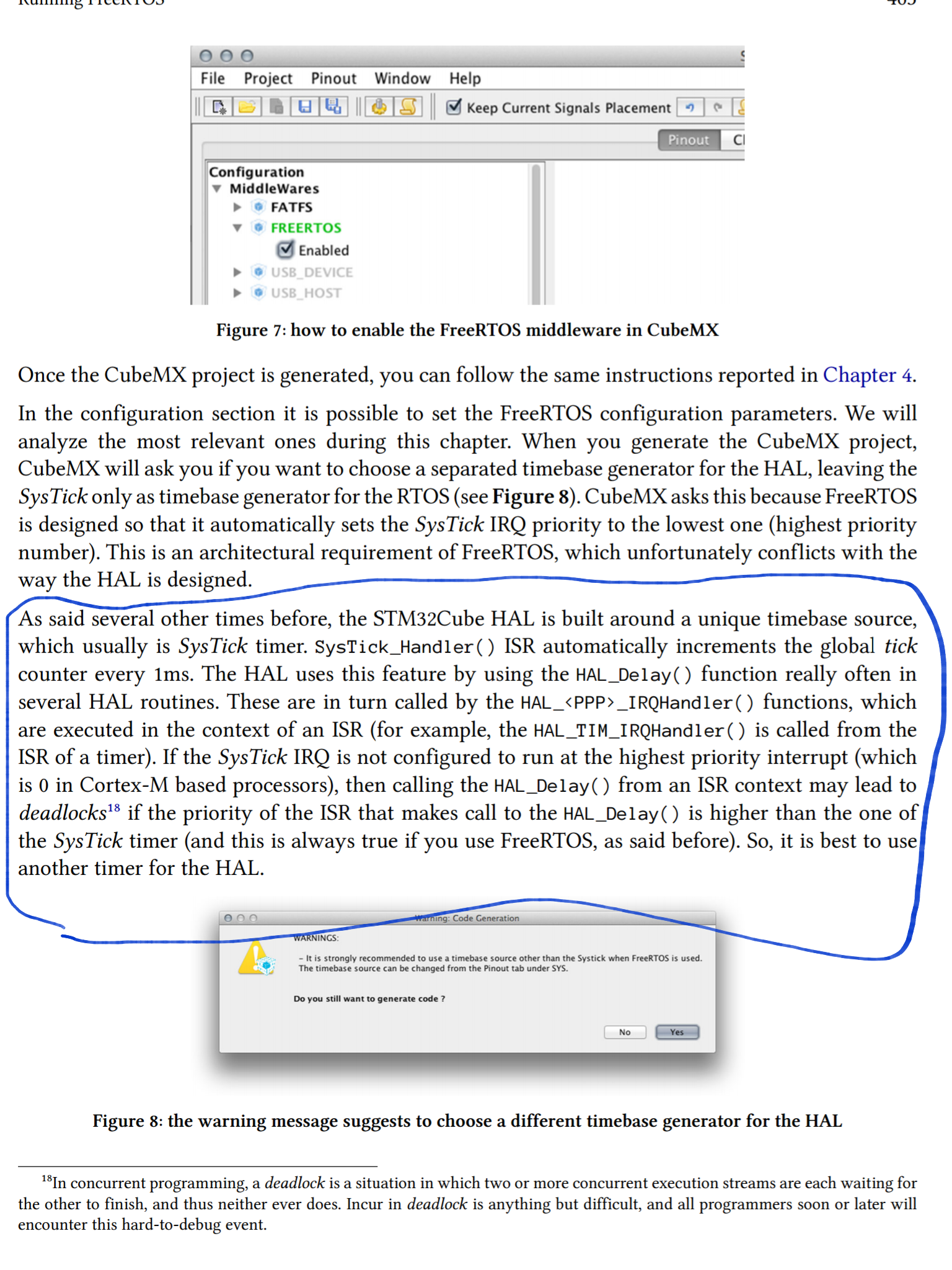
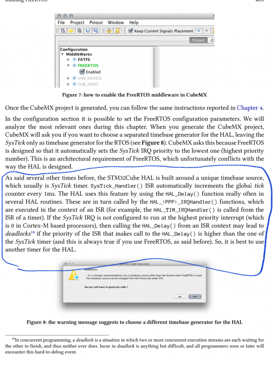
I've read the book about stm32/freertos don't know something to do with RAW32 or not. Since I also use stm32 and also systick
-
Thank for quick respond! I use GNU ARM Embedded Toolchain 5-2016-q3-update , or 5.4.1 20160919 to be exactly. With Eclipse. For uGFX I use master branch download zip file from https://git.ugfx.io/uGFX/uGFX even I just try download while ago. Still same result I told you Hardfault on two thread (no thread or 1 thread there is no hardfault) Keep in mind that GFX_OS_USE_KEIL is not necessarily the correct setting when using Keil µVision. That setting is used when using the Keil RTX (CMSIS compatible) RTOS. It's possible to use any underlying system such as FreeRTOS or even just running baremetal in a Keil µVision project. The GFX_COMPILER and GFX_CPU macros are the ones you want to worry about in this case. For this I will try and also search into forum also. And I will let you know. To be clear. This issue is coming from threading thing in RAW32 right? Meaning if I try switch Chibi os or freeRtos then it might no problem about this? I'm new to both RTOS so sooner or later I will try that. Maybe I start with freeRTOS 1st since there is more document and last time I try ChibiStudio I got a lot of error to fix and hunt. For now I try to stick and solve RAW32 1st.
-
I run demos\modules\gos\threads : If both threads then it hardfault (I place trace_printf in location of hardfault call routine) SEGGER J-Link GDB Server V6.12f - Terminal output channel thread 1 thread 2 thread main HardFault! If none thread then no problem SEGGER J-Link GDB Server V6.12f - Terminal output channel thread main thread main thread main thread main thread main If either 1 thread then also no problem SEGGER J-Link GDB Server V6.12f - Terminal output channel thread 1 thread main thread 1 thread 1 thread main thread 1 SEGGER J-Link GDB Server V6.12f - Terminal output channel thread 2 thread main thread 2 thread main thread 2 thread 2 thread main So that meaning of this? Thread don't work properly? Cause of this is? RAW32 have problem? Systick setting have problem? I guess that is relate to demo/tools/touch_raw_reading right? But how come demo/tools/touch_driver_test ?
-
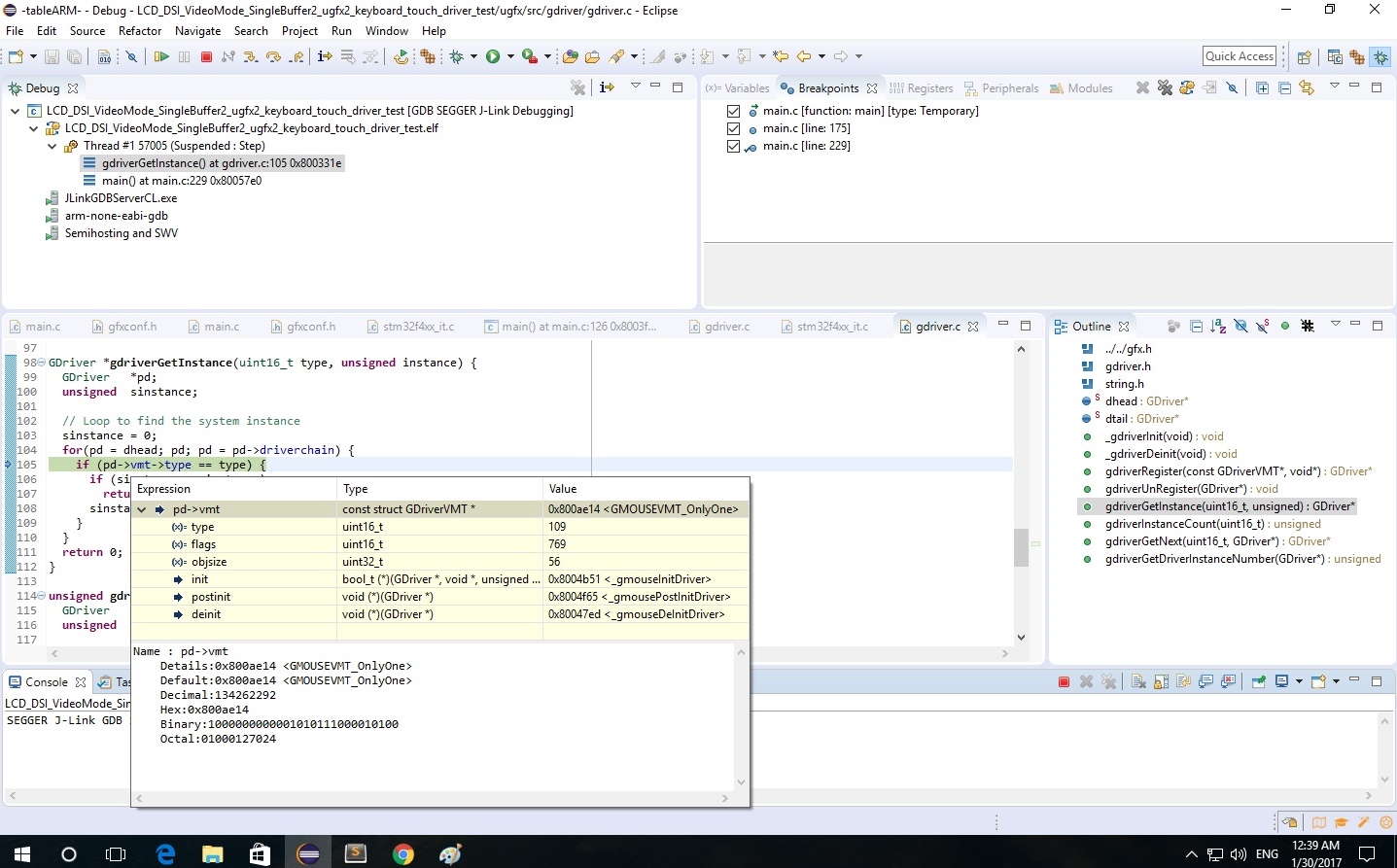
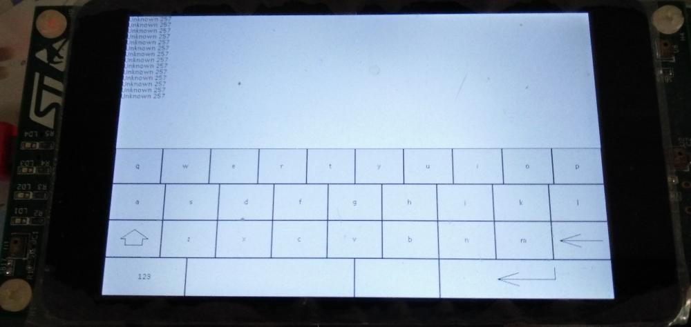
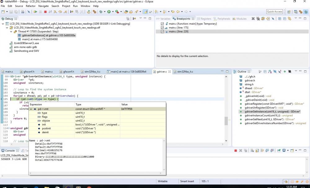
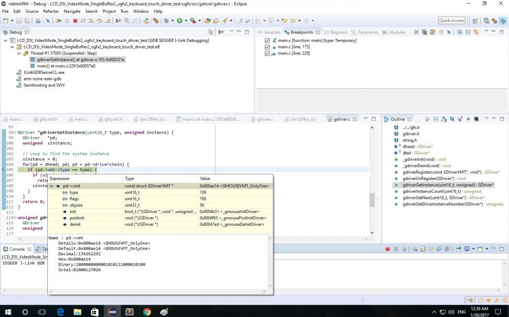
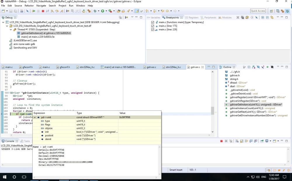
Problem with hardfault. Still don't know why? I use RAW32. I try with: /demos/tools/touch_calibration_brabber /demo/tools/touch_driver_test /demo/tools/touch_raw_readings All can compile without error. The touch_calibration_brabber and touch_raw_readings got HardFault exception at same line : m = (GMouse *)gdriverGetInstance(GDRIVER_TYPE_MOUSE, 0); For touch_driver_test can run without HardFault on that problem line with previous 2. But when I try to delete the rest of program start from this line to the end, in another word retain code only beginning until this line just for test/isolate problem. Then I get HardFault! Just same file only I delete the rest then HardFault come!? How can this be? Where the problem come from? I try to step into those line , it seem before hardfault , compiler can't see the value of type. So after this line: if (pd->vmt->type == type) { it jump to hardfault. But touch_driver_test when it run compiler seem to see value of type like the picture below. But I don't know when I just delete the rest of program can try compile then the 3 picture , no longer can see value of type. The driver seem to work even not yet full range since I get reading value show in touch_driver_test. Only problem is about the hardfault. What cause of this? How to solve?
-
Welcome. Joel. Just let me know. So that I can improve. Now I going to make touch panel to work in this board. By start with board file and c file of Maytham. I got hardfault error in 2 of demo-program but 1 test-driver is working. I will track down to it. Reading from wiki page tell me that calibration will show each time power-on or initial ugfx right? For demo-programs I try there is no calibration appear. Can I call function from runtime? Or do I need to implement the function myself? (Meaning is there a calibration function already exist ready to call?)
-
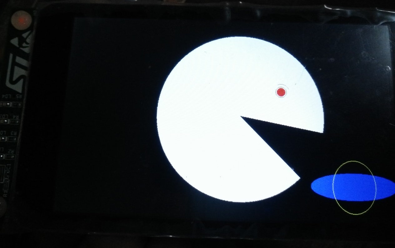
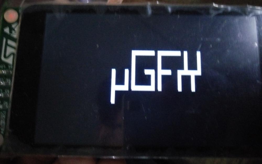
I can make it work like in picture. Thank to Maytham that I edited from him. And Joel Bodenmann , inmarket for suggestion. I add: undef Red, undef Green, undef Blue in board file , add DSI_HandleTypeDef hdsi_eval , declare uint32_t lcd_x_size and uint32_t lcd_y_size , clock LTDC in board file RCC->PLLSAICFGR = (STM32_PLLSAIN_VALUE << 6) | (STM32_PLLSAIR_VALUE << 28) | (STM32_PLLSAIQ_VALUE << 24); RCC->DCKCFGR = (RCC->DCKCFGR & ~RCC_DCKCFGR_PLLSAIDIVR) | STM32_PLLSAIR_POST; RCC->CR |= RCC_CR_PLLSAION; and DSI_PHY_TimerTypeDef PhyTimings; /* Configure DSI PHY HS2LP and LP2HS timings */ PhyTimings.ClockLaneHS2LPTime = 35; PhyTimings.ClockLaneLP2HSTime = 35; PhyTimings.DataLaneHS2LPTime = 35; PhyTimings.DataLaneLP2HSTime = 35; PhyTimings.DataLaneMaxReadTime = 0; PhyTimings.StopWaitTime = 10; HAL_DSI_ConfigPhyTimer(&hdsi_eval, &PhyTimings); and strange thing is LcdClock = 30000 instead 27429 then it work!? No offset anymore. I think it something to do with sync-timing number or the calculating-code thing inside. If I use exact number 27429 as I set LCD clock to that , it will offset display. Once I give value more to 3000 issue seem to disappear. I track down the code in debug. This LcdClock is relate to calculate timing of parameter in LTDC so I think it cause it. this is main gdispDrawLine(0, 0, width-1, 0, White); //show up gdispDrawLine(0, height-1, width-1, height-1, White); //show down gdispDrawLine(0, 0, 0, height-1, White); //show left gdispDrawLine(width-1, 0, width-1, height-1, White); //show right If you guy have time try to test my files. And please comment. Now I going to try and play with touchscreen. (PS. I work with Eclipse and GNU ARM wit baremetal what tools you guy use to work in ARM? Text editor and Makefile? ) board_STM32LTDC.h gdisp_lld_STM32LTDC.c
-
By the way can I ask stupid question? Since resolution of TFT is 800x480 (widthxheight) So if drawing I can do is from 0,0 to width-1,height-1 am I right? Meaning 0,0 to 799,479 If 0,0 to 800,480 then resolution will be 801x481pixels... If correct I think I can make it already.
-
Or maybe I need check my systick equal 1ms or not? Something to do with systick? I never check it yet. I only check DSI clock, LTDC clock
-
Hi Maytham thank for reply. For your info I'm outside I will investigate more tonight. I use values from ST example HAL VSA = OTM8009A_480X800_VSYNC; /* 12 */ VBP = OTM8009A_480X800_VBP; /* 12 */ VFP = OTM8009A_480X800_VFP; /* 12 */ HSA = OTM8009A_480X800_HSYNC; /* 63 */ HBP = OTM8009A_480X800_HBP; /* 120 */ HFP = OTM8009A_480X800_HFP; /* 120 */ Clearly it make offset large , once I change back to your value HSA from 63 > 120. I much better. Still 2-3pixel offset horizaltal/vertical. As the dirty-workaround I do that I get picture below is. gdispDrawLine(0, height-1, width, height-1, White); //show up gdispDrawLine(0, height-2, width, height-2, White); //show down gdispDrawLine(width-2, 0, width-2, height, White); //show left gdispDrawLine(width-3, 0, width-3, height, White); //show right It seem that you enable clock in gdisp_lld_STM32LTDC.c But I remember that I do quite difference from you. I enable clock in board_STM32LTDC.h file and comment out clock enable in gdisp_lld_STM32LTDC.c You seem to set LTDC clock by assign PLLSAIR only. How can LTDC clock can be set correctly and enable? There no need to assign PLLSAIN, PLLSAIR_POST and RCC->CR |= RCC_CR_PLLSAION? Or there is somewhere else you do in main.c? I got black screen if I remember correct. So I try set clock of LTDC in board_STM32LTDC.h this : // KoD LCD clock configuration // PLLSAI_VCO Input = HSE_VALUE/PLL_M = 1 Mhz // PLLSAI_VCO Output = PLLSAI_VCO Input * PLLSAIN = 384 Mhz // PLLLCDCLK = PLLSAI_VCO Output/PLLSAIR = 384/7 = 54.857 Mhz // LTDC clock frequency = PLLLCDCLK / LTDC_PLLSAI_DIVR_2 = 54.857/2 = 27.429Mhz #define STM32_PLLSAIN_VALUE 384 #define STM32_PLLSAIQ_VALUE 4 #define STM32_PLLSAIR_VALUE 7 #define STM32_PLLSAIR_POST STM32_SAIR_DIV2 RCC->PLLSAICFGR = (STM32_PLLSAIN_VALUE << 6) | (STM32_PLLSAIR_VALUE << 28) | (STM32_PLLSAIQ_VALUE << 24); RCC->DCKCFGR = (RCC->DCKCFGR & ~RCC_DCKCFGR_PLLSAIDIVR) | STM32_PLLSAIR_POST; RCC->CR |= RCC_CR_PLLSAION; What do you think? I will more investigate tonight.
-
Really don't know why it seem to offset from 0,0
-
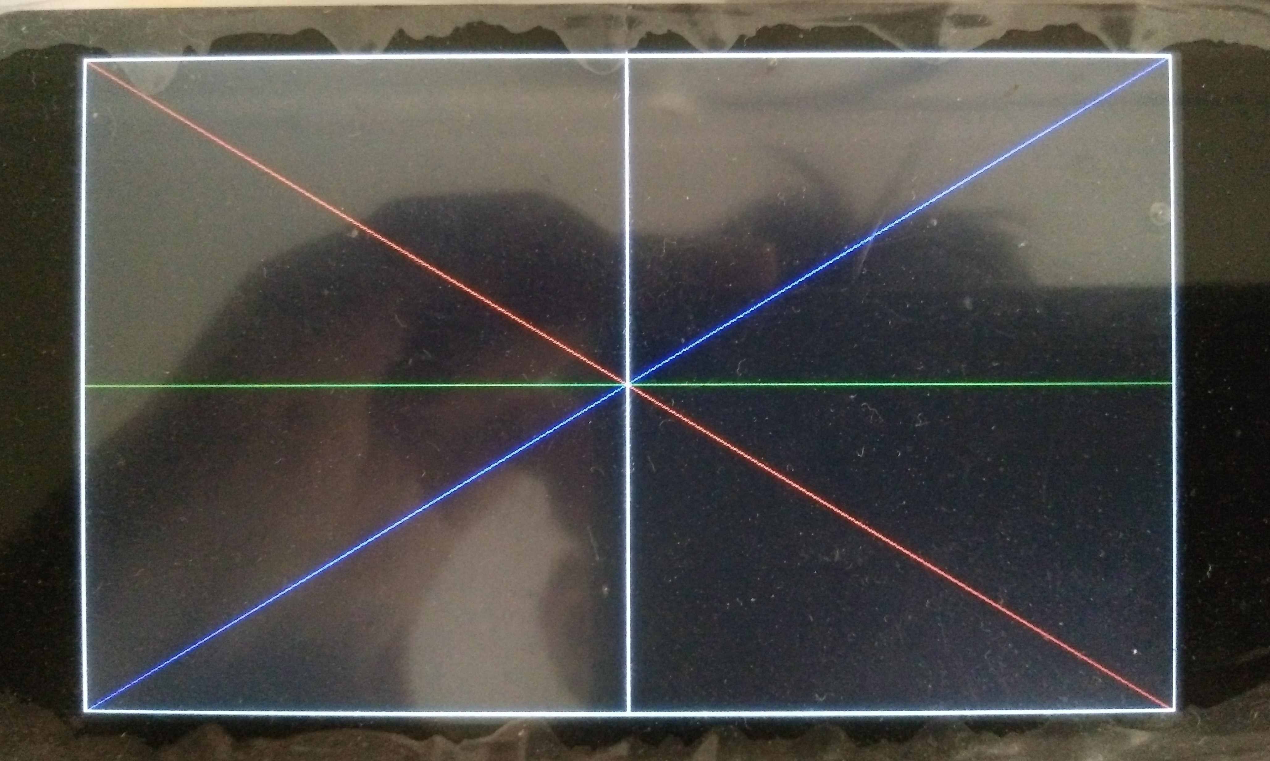
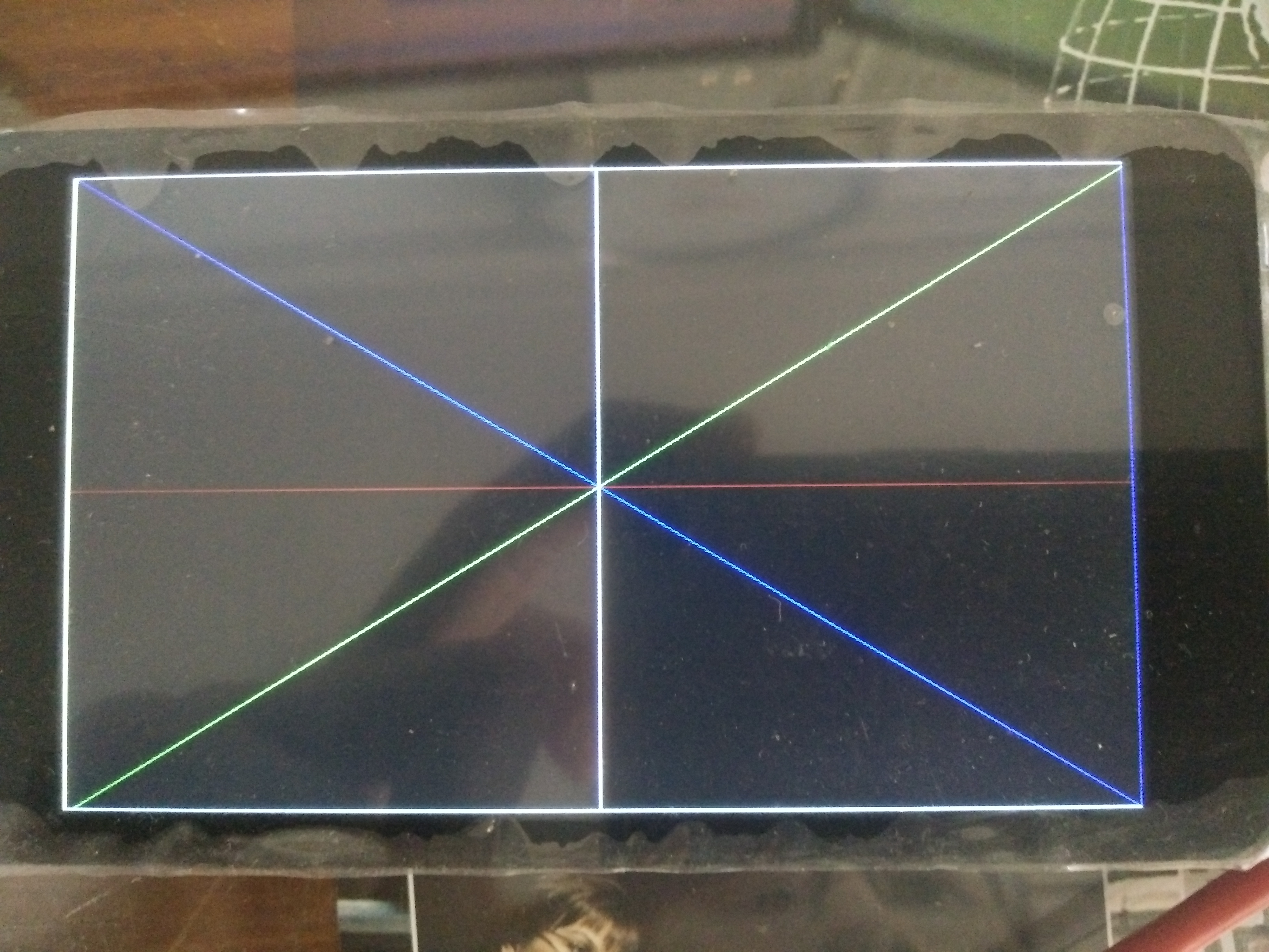
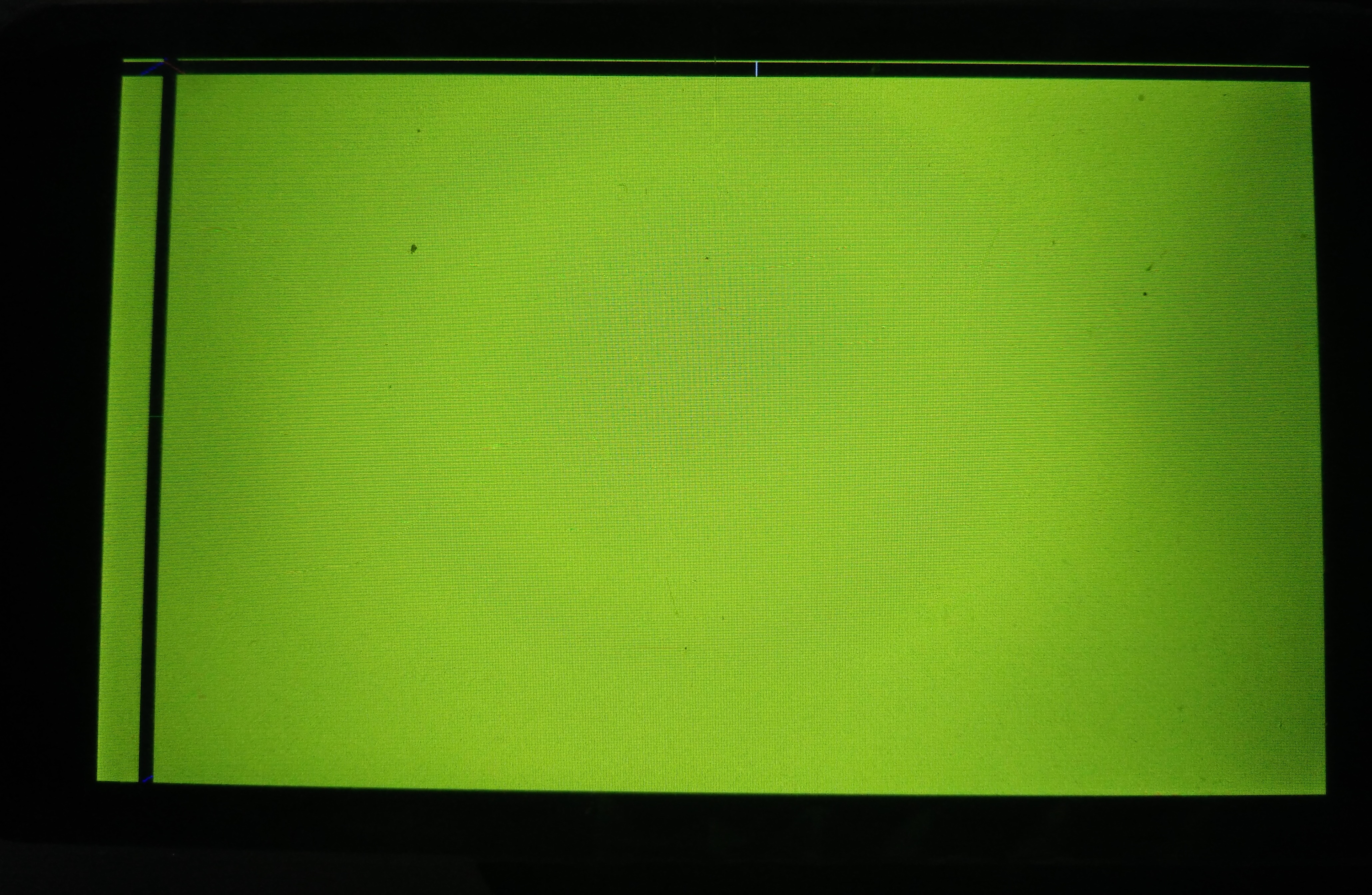
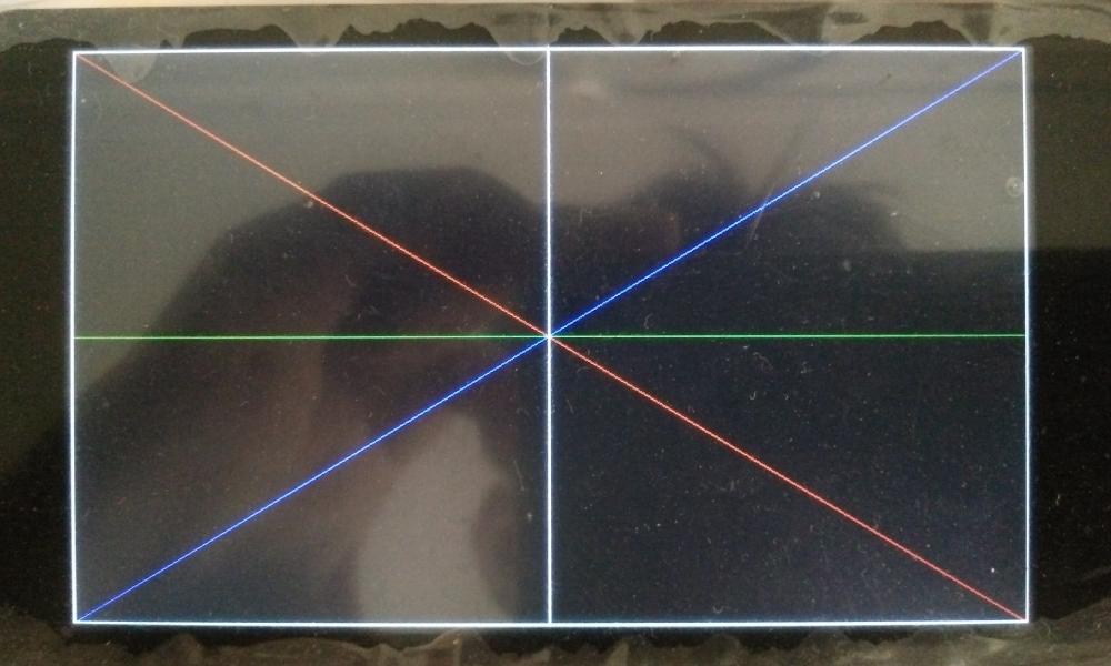
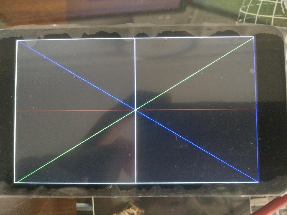
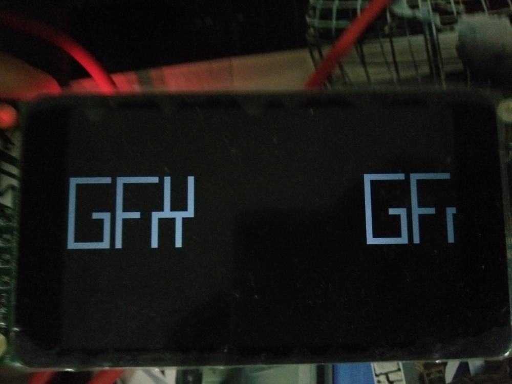
I've checked for long time. Clock is cause of that image like non-smooth. This is what I do : 1.) Add LTDC clocking setting into init_board(GDisplay* g) It seem like gdisp_lld_STM32LTDC.c don't set it Without add this I got black screen. Once I add code it show picture as normal. /* LCD clock configuration */ /* PLLSAI_VCO Input = HSE_VALUE/PLL_M = 1 Mhz */ /* PLLSAI_VCO Output = PLLSAI_VCO Input * PLLSAIN = 384 Mhz */ /* PLLLCDCLK = PLLSAI_VCO Output/PLLSAIR = 384 MHz / 7 = 54.857 MHz */ /* LTDC clock frequency = PLLLCDCLK / LTDC_PLLSAI_DIVR_2 = 54.857 MHz / 2 = 27.429 MHz */ PeriphClkInitStruct.PeriphClockSelection = RCC_PERIPHCLK_LTDC; PeriphClkInitStruct.PLLSAI.PLLSAIN = 384; PeriphClkInitStruct.PLLSAI.PLLSAIR = 7; PeriphClkInitStruct.PLLSAIDivR = RCC_PLLSAIDIVR_2; HAL_RCCEx_PeriphCLKConfig(&PeriphClkInitStruct); 2.) Change value of "Horizontal, Vertical sync (pixels)" static const ltdcConfig driverCfg = { 800, 480, // Width, Height (pixels) 120, 12, // Horizontal, Vertical sync (pixels) 120, 12, // Horizontal, Vertical back porch (pixels) 120, 12, // Horizontal, Vertical front porch (pixels) 0, // Sync flags 0x000000, // Clear color (RGB888) from 120, 12, // Horizontal, Vertical sync (pixels) to 63, 12, // Horizontal, Vertical sync (pixels) This value come from file stm32469i_discovery_lcd.c /* The following values are same for portrait and landscape orientations */ VSA = OTM8009A_480X800_VSYNC; /* 12 */ VBP = OTM8009A_480X800_VBP; /* 12 */ VFP = OTM8009A_480X800_VFP; /* 12 */ HSA = OTM8009A_480X800_HSYNC; /* 63 */ HBP = OTM8009A_480X800_HBP; /* 120 */ HFP = OTM8009A_480X800_HFP; /* 120 */ For some reason if I use same value 120,12 it will black-screen. Once I change it show as normal. But here is problem. Look like screen is offset to the down and right. I don't know why. I guess it is something to do with LTDC init, DSI init either on board file or gdisp_IId_STM32LTDC.c file. Pictures show that I fill 10pixel of the edge but display show other thing shift to the down-right. I don't know where to look for now, have done and try a lot already. Please help. How or Where to solve this, what cause this? This is in my main.c // Get the screen size width = gdispGetWidth(); height = gdispGetHeight(); trace_printf("width= %d\n", width); trace_printf("height= %d\n", height); // Code Here gdispDrawLine(0, 0, width, height, Red); gdispDrawLine(0, height, width, 0, Blue); gdispDrawLine(0, height/2, width, height/2, Green); gdispDrawLine(width/2, 0, width/2, height, White); gdispFillArea(0+10, 0+10, width-10, height-10, Yellow);

-
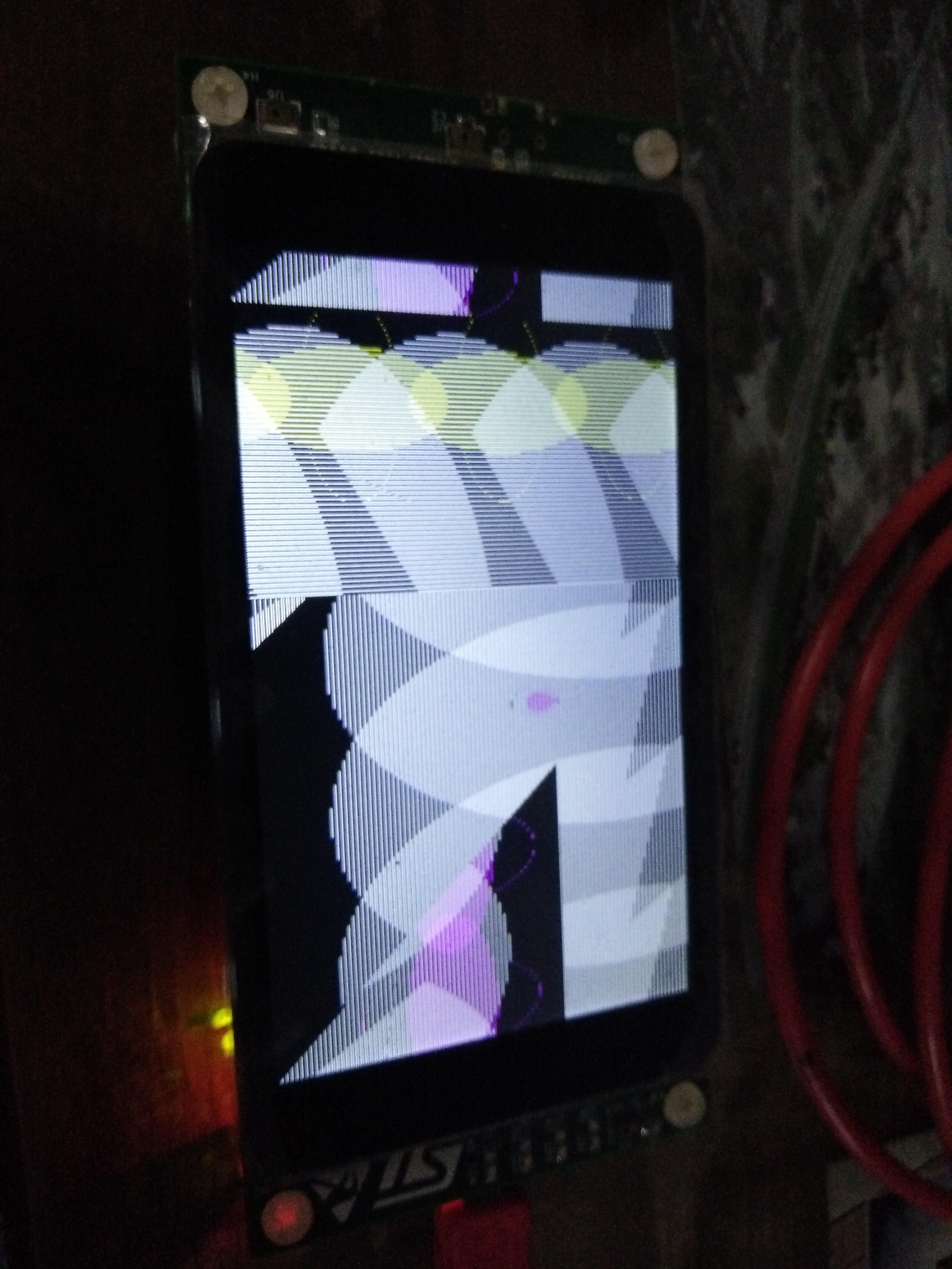
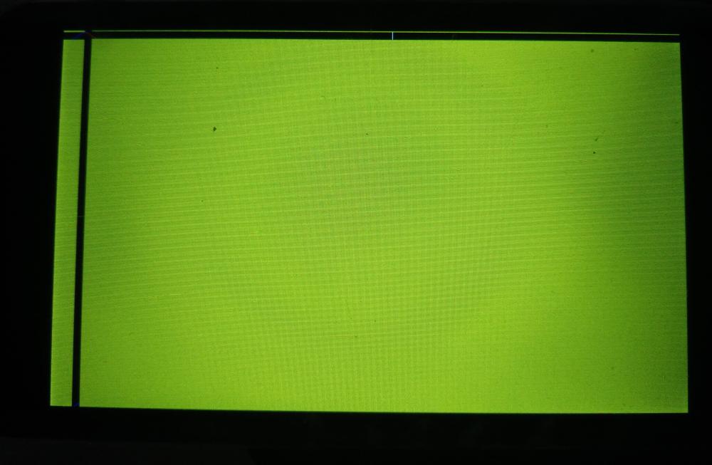
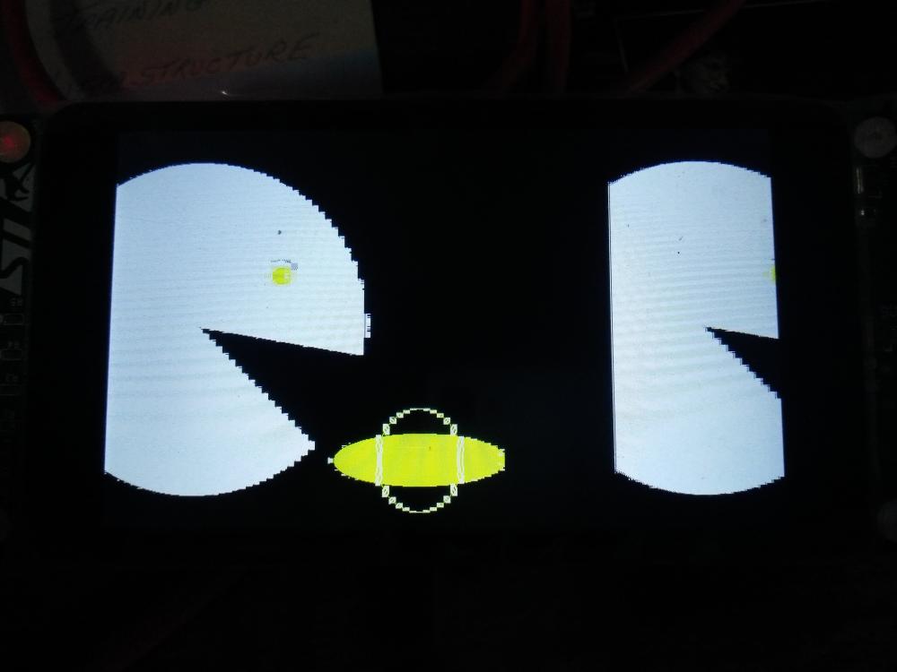
I do try change PeriphClkInitStruct.PLLSAI.PLLSAIR = 5; to PeriphClkInitStruct.PLLSAI.PLLSAIR = 4; I got this. I've no idea what I've done. Guess is clock setting is not correct. What really happen? And also seem to not in sync or something.
-
I think I have a clue. I maybe about DSI and/or LTDC clock initial... /* STM32F4xx HAL library initialization: - Configure the Flash prefetch, instruction and Data caches - Systick timer is configured by default as source of time base, but user can eventually implement his proper time base source (a general purpose timer for example or other time source), keeping in mind that Time base duration should be kept 1ms since PPP_TIMEOUT_VALUEs are defined and handled in milliseconds basis. - Set NVIC Group Priority to 4 - Low Level Initialization: global MSP (MCU Support Package) initialization */ HAL_Init(); /* Configure the system clock to 180 MHz */ SystemClock_Config(); // ugfx // // test clock // /* LCD clock configuration */ /* PLLSAI_VCO Input = HSE_VALUE/PLL_M = 1 Mhz */ /* PLLSAI_VCO Output = PLLSAI_VCO Input * PLLSAIN = 417 Mhz */ /* PLLLCDCLK = PLLSAI_VCO Output/PLLSAIR = 417 MHz / 5 = 83.4 MHz */ /* LTDC clock frequency = PLLLCDCLK / LTDC_PLLSAI_DIVR_2 = 83.4 / 2 = 41.7 MHz */ PeriphClkInitStruct.PeriphClockSelection = RCC_PERIPHCLK_LTDC; PeriphClkInitStruct.PLLSAI.PLLSAIN = 417; PeriphClkInitStruct.PLLSAI.PLLSAIR = 5; PeriphClkInitStruct.PLLSAIDivR = RCC_PLLSAIDIVR_2; HAL_RCCEx_PeriphCLKConfig(&PeriphClkInitStruct); // end test clock // once I copy some clock-setting code from ST example function "LCD_Init" just before uGFX code: and also before BSP_SDRAM_Init(); Since I see SDRAM initial already in board_STM32LTDC.h Once try then LCD show picture like this. Still I need to solve why it so mess. Again, please help me solve