
Sting
-
Posts
77 -
Joined
-
Last visited
Content Type
Forums
Store
Downloads
Blogs
Everything posted by Sting
-
I am back trying to figure this out and all of the displays I can find have separate rgb and touch connectors. To really make this work, do I need to build a circuit board that on the input side has the 40 pin rgb connector and a 4 pin touch connector. On the output side has a 40 pin rgb connector to the STM board. The board just maps the touch connectors to the right pins from the input side to the output side? Then I would just need a flex cable to connect from this board to the STM device.
-
My question is more general but I will use the table or list widget as an example to talk about. I want my UI to be clean, there is only so much space on the display. What I want is to make the table or list widget a specific number of rows tall. Currently the height is governed by the number of pixels at creation time. But, only the developer knows how tall the title or the headers are for the table widget, so it is nearly impossible to get the device to look clean. And only the developer knows how high the row is because of row padding. How is this expected to be handled in the development process. Is this expected to be available in the documentation. Should it be added to the documentation block for the create function?
-
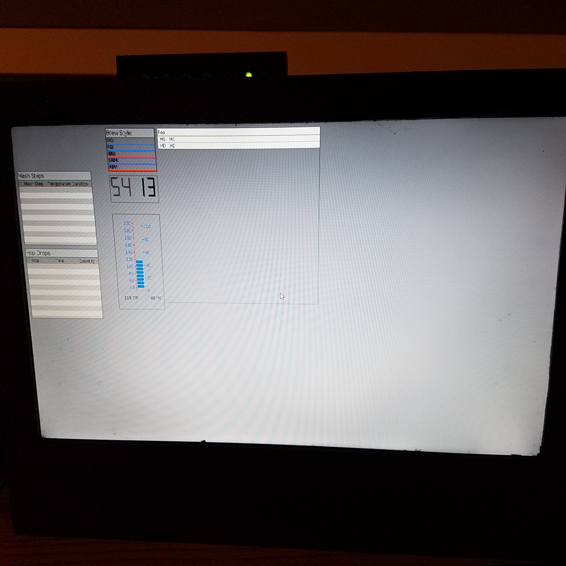
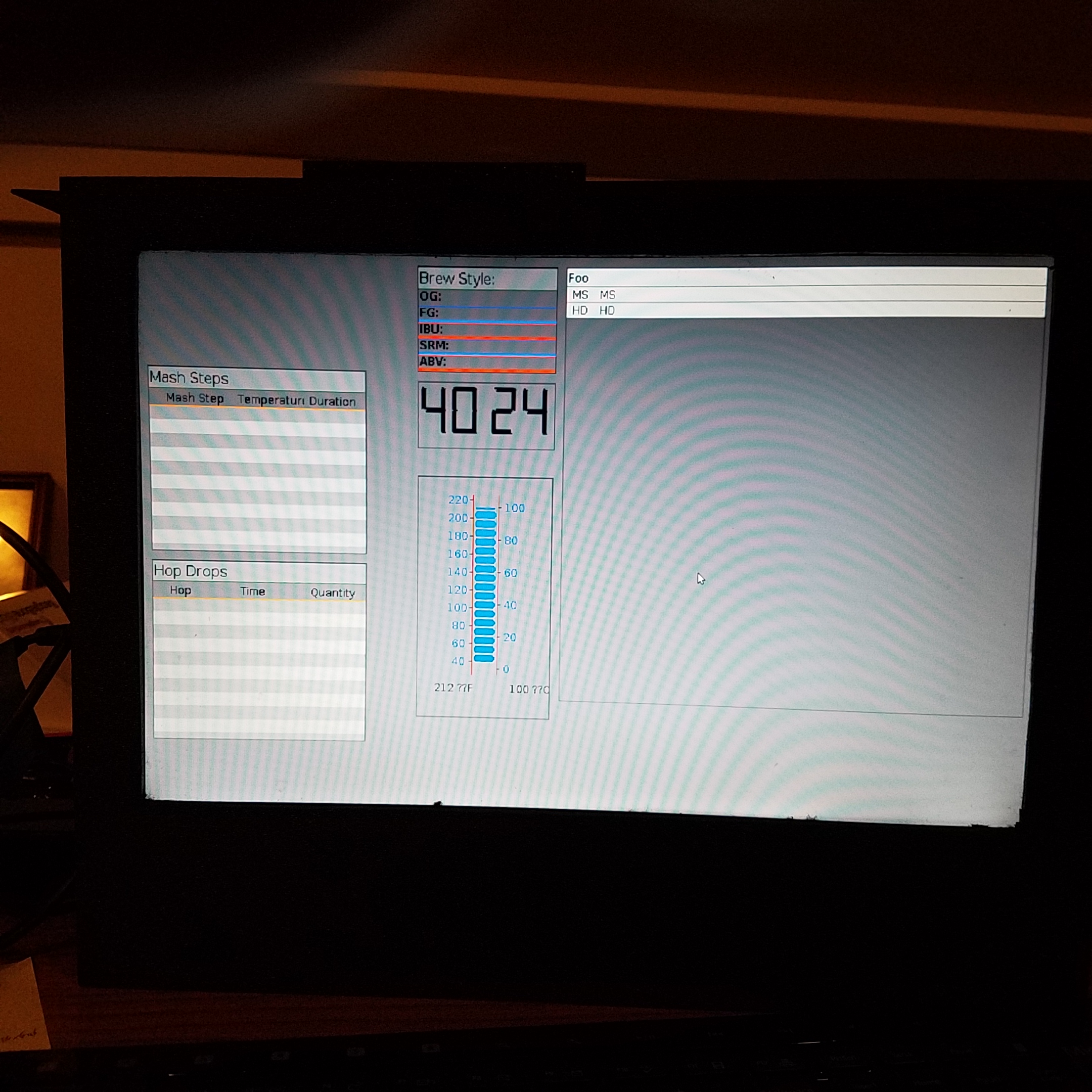
I wouldn't mind sharing the temperature gauge but at this point it is just hacked together. It is fixed width and height ans all of the positions are hard coded to fit. When I get to making it real I will let you know. As for the table widget, I had to make more changes to make it work better. The remaining portion of the display used to be just background color when the even/odd background was used so with no rows it was a solid color. Now the remaining area is colored in rows of even/odd. I also want to add something to allow the developer to make better use of the columns. As a simple start I will try an api like: gwinTableSetColumnWidth(xx, uint16_t column, uint16_t width) But I haven't worked out the geometry yet, what to do with the extra space if the width is greater then sum of the column widths or what to do if the sum is greater then the width. Another option I thought of is that as each row is added the columns are checked such that each column width is as large as is needed to hold the widest content. Then if the content is larger then the width of the table, only the last column is truncated with ellipses. I haven't decided what to do yet, but currently the table does not make good use of space. For the Mash Step table, the name column needs to be big and the other two columns are at most 6 char's wide. The table could be much less wide if I had a good way to deal with the column width. Of course, to make this good I would have to change the names in the headers.
-
I have been trying to decide how to make my current project work well on an embedded linux machine. I decided to try a smaller scale X11 window manager, I tried Matchbox as a starter. I set it up to run my brewery project compiled with ugfx. It is the only application running, there are no menu's to load other application. I have full access to all of SDL2 and even openGL if I want. All of the daemons are running, it has access to the network, and the PostgreSQL database on the machine. It is running on a display that is 1440x900 resolution, it is scaled from the application that is built with resolution 1024x600. Rebuilt the application for bigger then the display resolution. I made an error ant typed in 1770 instead of 1440. There is just less room on the right. The display isn't the best and it is too big. It is a display from a defunct laptop with an HDMI adapter that I bought on ebay for $30 or so. Anyway, it was fun to do and I will work on using an even smaller window manager this week. The tinyWM is the smallest they come and provides no service. The good part is it will filter less keyboard and mouse and will consequently run faster. Sorry for the huge images.
-
@joel Seriously, I wasn't offended. My wife also accuses me of changing the plan all the time. I have very little loyalty to the past if I can't see a path to where I want to go. About finding a display and touch panel separately: Because I don't want to build a board for this project, due to my qualifications, I looked for a flex connector that would be like the one that is on the display that came with the STM32F7 and couldn't find one. Maybe I didn't look hard enough. Since I couldn't find something I had to rule this out. For the business project I will be able to get my partner to build the connector, and he is waiting to see how my personal projects pan out before he is willing to participate. @Inmarket What would I get in the Raspberry Pi that I don't get in the Jetson TK1. From my perspective the benefit would be performance. The Brewery is a very simple device. I have built most of it on a Arduino Uno. Basically it has to measure temperature and use pwm to control a solid state relay to boil water. The difficult parts are: controlling the temperature +- 1 degree and halting the progress of the temperature at specific points for some time period. The reason why the Uno didn't work was because of the display issue. I have many different micro controllers and many different micro pc's. If I knew I would get something from the Pi that the Jetson wouldn't do I would switch. One problem with the micro pc approach is that because it is linux reading the temperature from the DS18B20 temperature sensors is accomplished using sysfs. Each thermometer takes about 1 second to get the temperature. This is way better on the Arduino and other such controllers because the temperature reading/translation can be done in two steps and one can read 8 thermometers in the same second. This is the main reason why I want to use the STM32F7 for the fermentation device. The fermentation device can ferment up to 6 different brews simultaneously and even though a second is a long time in these kind of devices, taking 7 seconds to measure all of the temperatures, 6 fermentations and the controlling device, seems excessive. There is very little user interaction other then setting the goal temperature for a specific fermentation so a smaller display could be used.
-
I am changing until I can find something I can work with. I don't think I have changed too many times. I started on the beaglebone black which would never really work. It does not support SDL2 and hence is very slow. It can't run raw, without linux, and access to all of the gpio and other features of the board would be unavailable. I then tries the STM32F7 and I still want to use this board. I spent two weeks looking for a display that would meet the design for the project and found few available larger displays. This is still something I would consider if I found a reasonable display. I am not a hardware designer, I have never build a pcb and am not comfortable that I would be successful. I had the Jetson TK1 laying around and I can make it work. I looked at those boards you referenced and none will meet my needs. The minimum I need is a 1024x600 RGB with a touch screen. The 1024x768 doesn't have a touch screen and the ones with a touch screen are not big enough. I am not comfortable that I could be successful building a board that could bridge between the display. Most of the boards this size seem to be LVDS, many have a 50 pin connector. I do plan to use the STM32F7 for the fermentation station because that device needs a smaller display. The change to the jetson allows me keep making progress and if in the interim I find a display that works I will go back. I intend to use the stm32F7 in a project because I have a production project I would like to use it for. The production project also requires a larger display, so I will continue to look.
-
I kind of had to take a step sideways, I am still looking for a display to use with STM32 board, but is is not as urgent as it was. I happen to have a Jetson TK1 board laying around that I did some parallel processing projects on and it happens to support SDL2 so I decided to use it. It makes the brewery a different kind of project, it will still use uGFX. I have uGFX running on SDL2 and the project is cross compiled from a linux machine, so thats all good. It is much faster then the linux frame buffer project. The part I am not so happy about is it has to run in X. The processor is better, it is a quad core Cortex A15 running at 2.X MHz. The added benefit is it has 192 GPU cores, and has a sata port to enable me to run a real database on a solid state drive. Not exactly an embedded project, but close..
-
I am having trouble with my laptop so it took me longet to get this here. Sorry if it inconveniences anyone. uGfxTable.tar
-
I am trying to find a display that I can use for my projects and could use some advise. The stm32f7 Discovery lcd pinout seems to be the standard RGB interface. There are not many displays that have the lcd and the capacitive touch screen combined in the same RGB cable. You will see by this post that I am really a software guy and need this to fit together fairly easily. One display I would like to use has two pin issues. http://www.hotmcu.com/101-inch-1024x600-tft-lcd-display-with-capacitive-touch-panel-p-215.html?cPath=6_16 The issues are: 1) Both pin 1 and 2 are both backlight vdd on the display and the pins on the stm32f7 are pin 1: vbl- and pin 1 vbl+. I don't know if it is a typo, I asked the manufacturer and they sent me the same information that is on the web page. 2) Pin 35 on the display is a pwm backlight control and on the stm32f7 the pin is GND. I assume tying this pin to gnd on the display would make the backlight display black. I asked the manufacturer about this and got no response. Is this assumption true?
-
Sorry, the pinout was there all along. All it took was someone who understands to point it out. Sorry for the bother. I have the pdf if anyone wants it.
-
The schematic files can be downloaded from: http://www.st.com/content/st_com/en/products/evaluation-tools/product-evaluation-tools/mcu-eval-tools/stm32-mcu-eval-tools/stm32-mcu-discovery-kits/32f746gdiscovery.html I did this and there is one pdf that I can read and it tells the content of some of the pins but there is no order, it seems that power and ground are missing. All of the other files are in schdoc format and I don't have altium installed to read them. I will install a trial version if I have to, but would rather not. I am a software guy, I do some vhdl firmware, but no hardware. I have a friend that might be able to read them and generate a pdf file for me.
-
I tried to go to the website of the manufacturer of the display and could not find the part number. My hope was that the display would show the pinout. I looked at other displays from other manufacturers that show the pinout for RGB interface and They did not match the Rocktech display I looked at. I will look at others. As well, all of the boards have 40 pin RGB connectors not 50 pin, this in any case some sort of adaptation will need to be done. If I could find the flex connector used on the stm32F7. I'm not sure replacing the display was in the design of this board. If anyone has any suggestions I would appreciate them.
-
I can't find the pinout of the connector on the STM32F7 discovery board. Most displays that come with a touch screen have the touch screen connector separate. I have found some displays that have the touch screen in the same connector and they have the connector pinout but I can't seem to be sure if they are compatible with the STM32F7 board. Does anyone know how to find the pinout of the connector on the board?
-
The touch panel is connected to the flex cable that connects the display to the board. I assume when I buy a new display it will have the same configuration and the flex cable from the display will have all of the pins needed. I am going to buy a 50 pin zif connector and solder it to the board then I will have more flexibility with the display size I need.
-
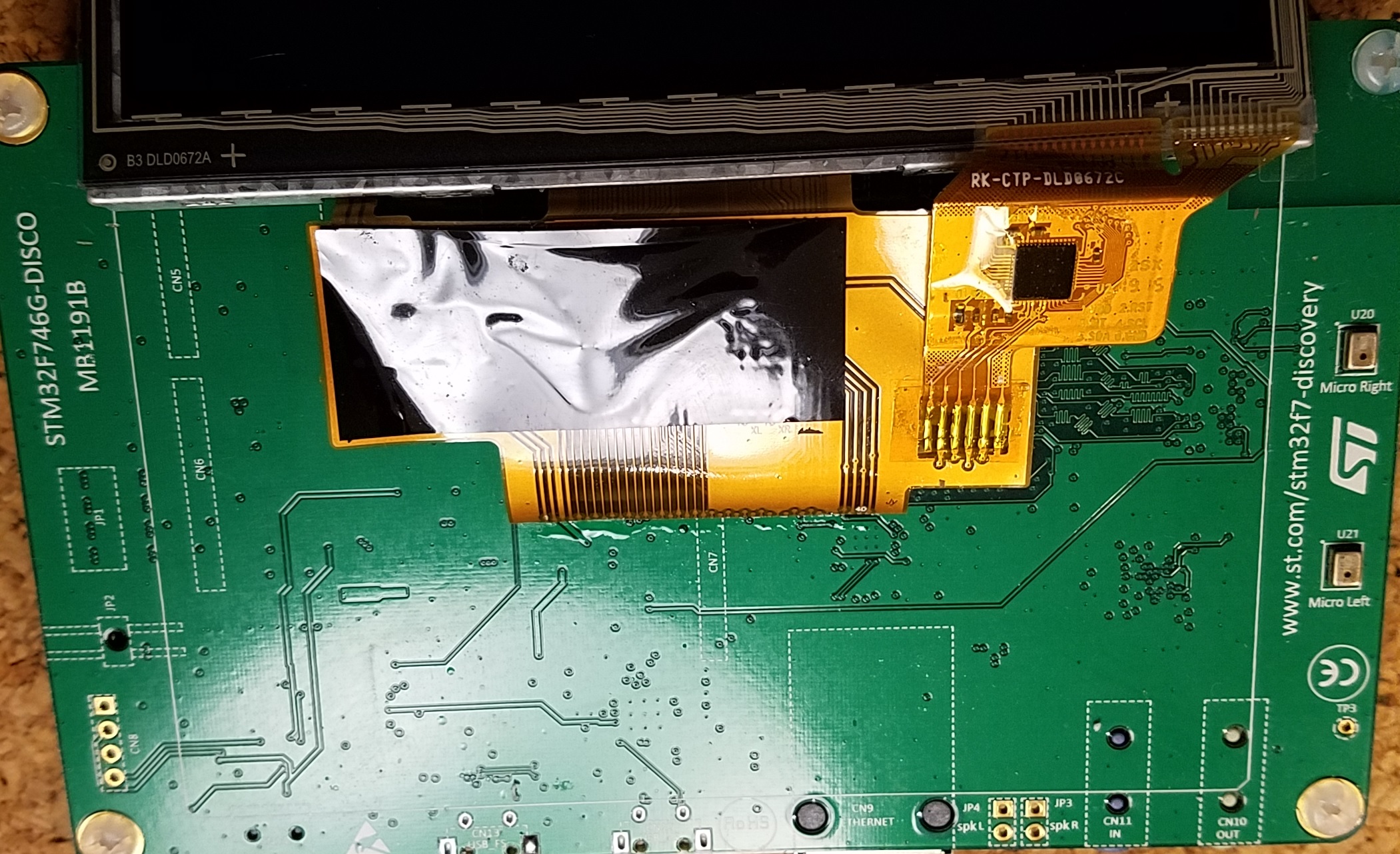
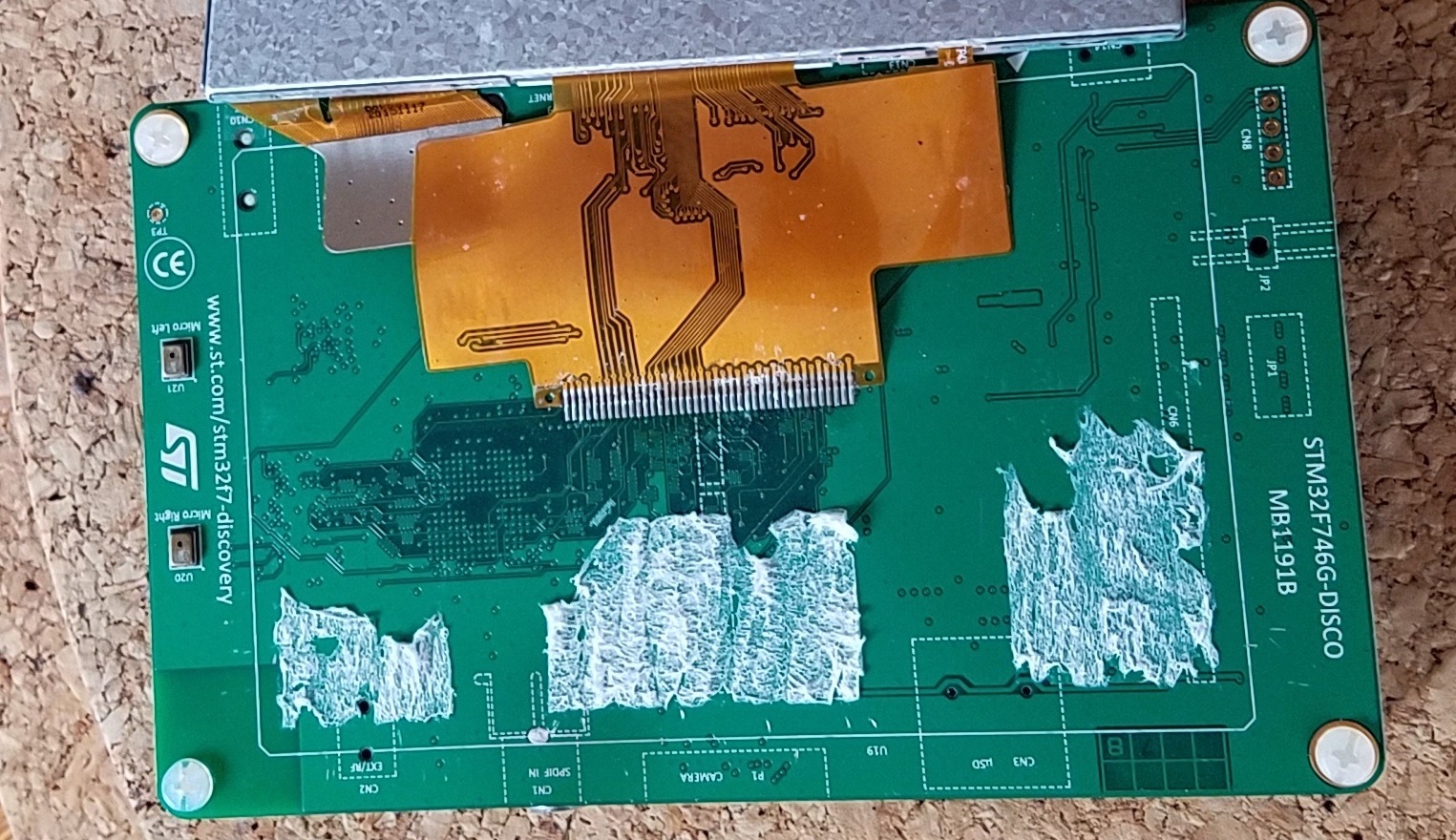
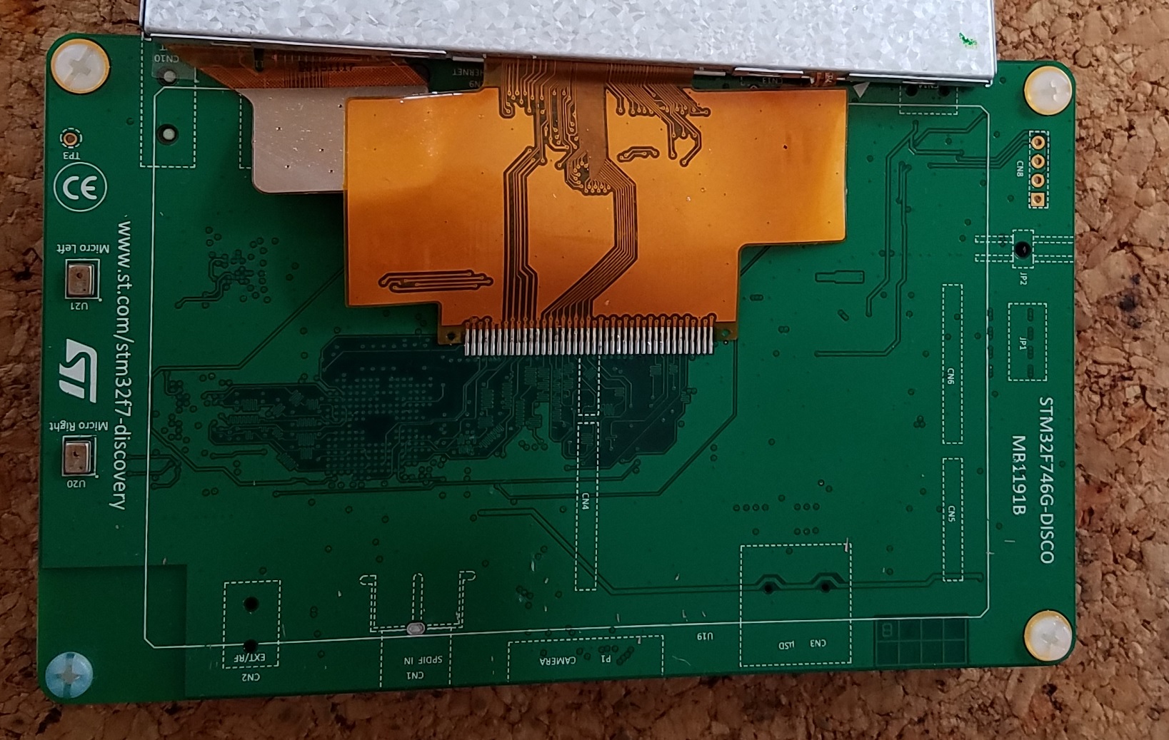
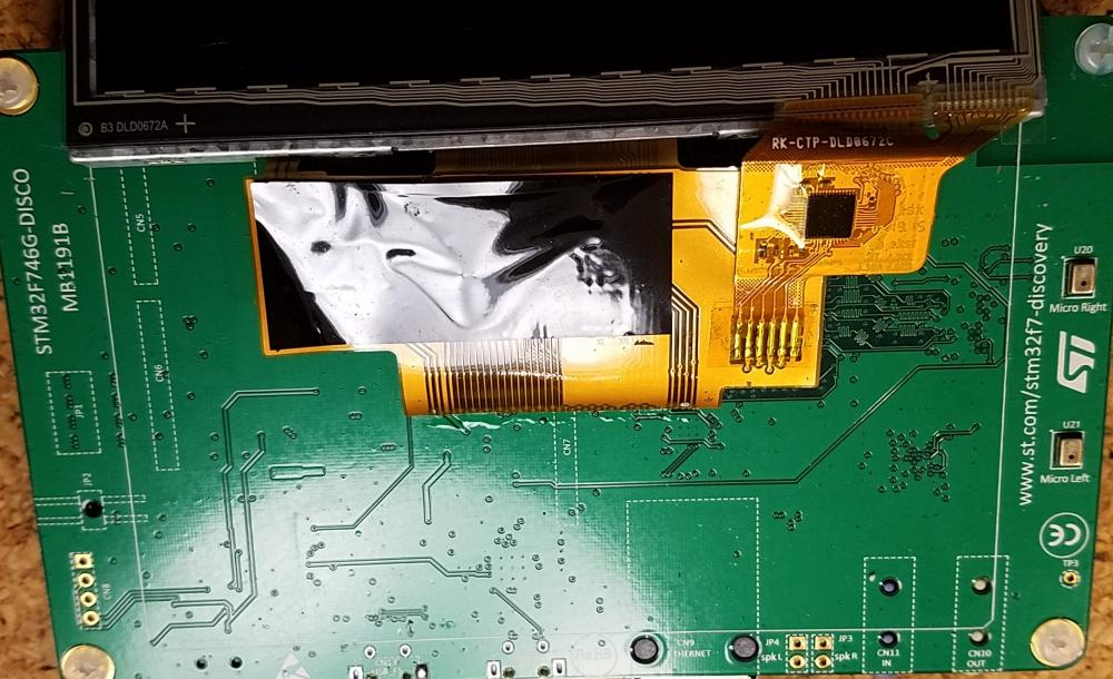
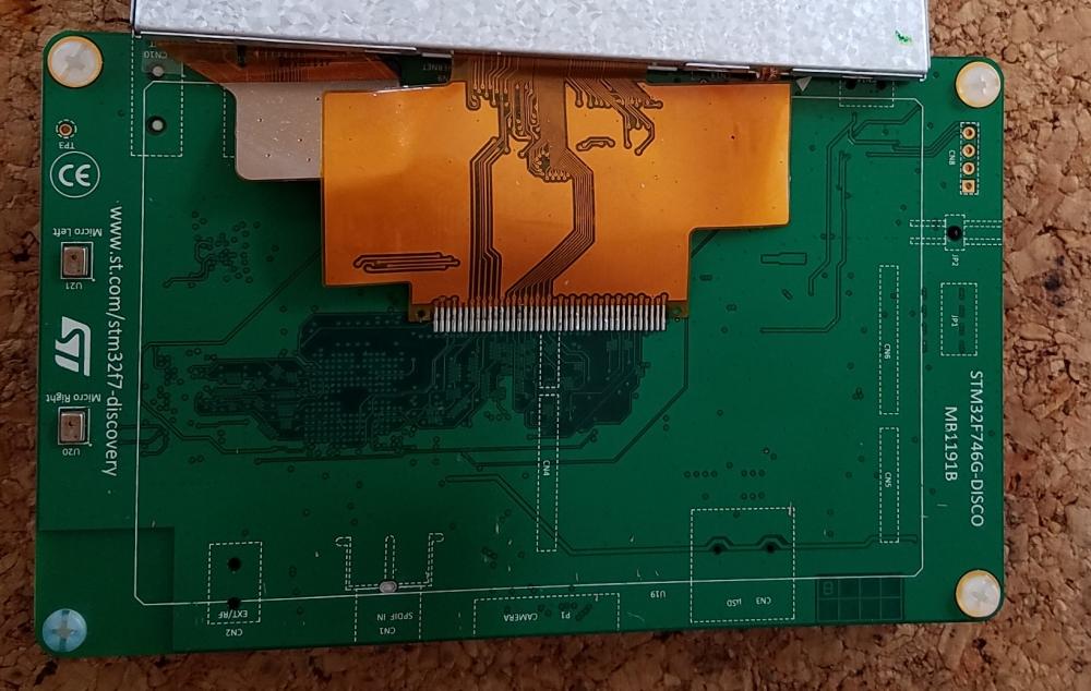
I took the display off from the STM32F7 Discovery that I won in the competition as I expect to use a much larger display. The process is easy enough but not trivial. The display is attached to the board by thick two sided tape. I used a small plastic screwdriver to split the tape by sliding the screw driver into the side of the tape. I used a round plastic pen to force the display away from the processor board. I do not have pictures of that process, If I do it again I will add some. Once I got the display off I used super goof off glue remover to reduce the stickiness of the tape. I used a tooth brush and my finger nails to remove the glue, and it takes some time as the glue is very sticky. I haven't removed the glue from the display at this point, I'm not sure what I will use it for. An image after the display was removed and before I removed the tape. What it looks like after I removed the tape.

-
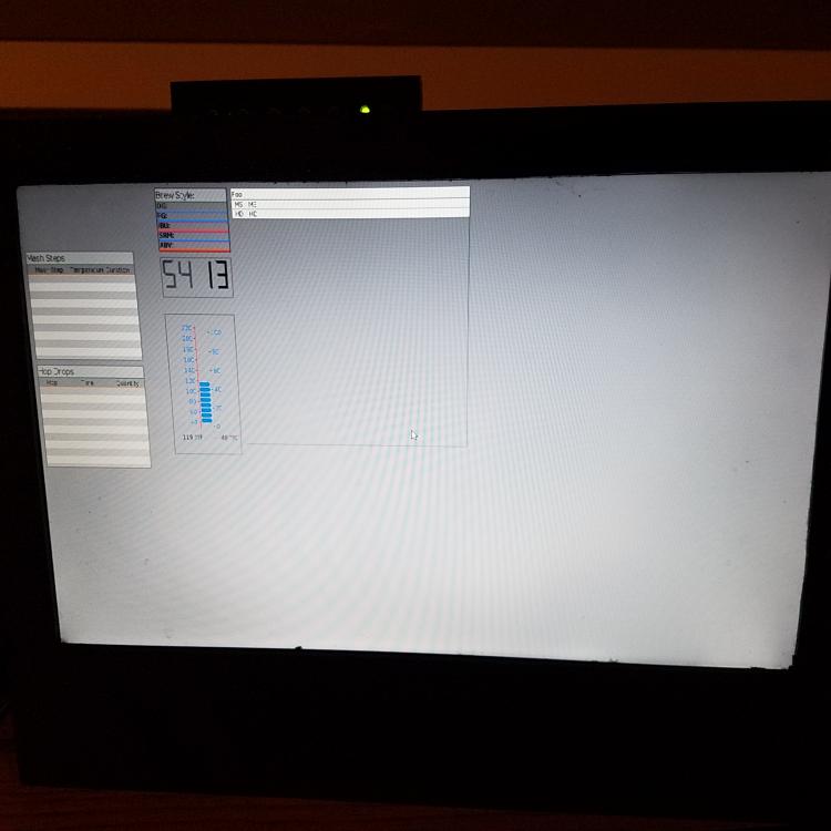
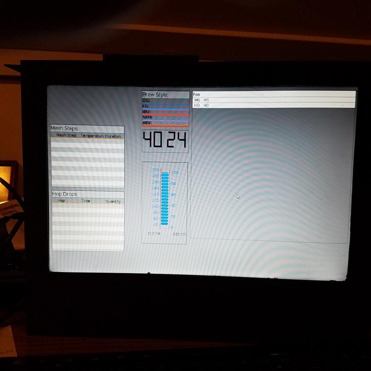
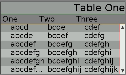
I am really making progress, I have to admit this is more complicated then the first project someone should pick for their first project on a new platform. I have most functionality tested. Test Matrix: I tested with the following set of features 1 2 3 4 5 6 7 8* Need Image No No No No No Yes Yes Yes Need Image Gif No No No No No Yes Yes Yes Need Table Images No No No No No No Yes Yes Need Table Embellishment Yes No No No No No No No Need Table Header Yes Yes No No Yes Yes Yes Yes Need Table Title Yes Yes Yes No No No No No Has Table Image No No No No No No No Yes Result Yes Yes Yes Yes Yes Yes Yes NO Test 8 has only a single row that has images and the problem is that the other rows don't paint the background where the image could go later correctly. I have included an image of the table that has the following: The title font is larger then the page font The title is right justified The image is scrolled down one row The image shows another issue where the header doesn't know that any rows have images. I know the fix for this and will implement it either later today after the football match or tomorrow.
-
It is getting a little out of control. I need to stop to work on some of my own components. I have implemented the following: ...SetTitle() ...SetTitleBackgroundColor() ...SetTtileFont() ...SetTitleJustify() ...SetHeader() ...SetHeaderBackgroundColor() Keeping track of the specific geometry is not difficult, but is tedious with all of the options and not storing intermediate state information. If I could do it at work I could be done by now
-
I am still working on the scrolling with/without title, with/without header, and making the geometry calculations more clear. I am also working to be sure that I make the footprint better with inmarket's previous post. I will be done by the end of the weekend, with lots of comments showing the details of the calculations.
-
Currently the widget style only covers color elements. I have built a table widget, a list widget already exists, and I plan to build others that have the need for at least one but maybe two alternative fonts. If more then one of these types of elements are on the same page it is left to the implementer to make the right choices to keep a consistent interface. The table has a title and a header, the list should have a header. And I will build a grid that is like a table but is cell oriented. What I was thinking was something like: #if GWIN_NEED_TITLE gwinSetStyleTitleFont (... gwinSetStyleTitleBackground (... gwinSetStyleTitleJustify (... #endif #if GWIN_NEED_HEADER gwinSetStyleHeaderFont (... gwinSetStyleHeaderBackground (... #endif Expanding the style concept would allow interfaces to be more consistent. Currently the table widget has the concept of even/odd background color for the rows and the list widget should have the same. If this could be conditionally added to the style then it would be straight forward for the implementer to create a consistent interface. Both the list widget and the table widget need to specify what kind of scrolling to enable for the device. How this is handled needs to be figured out, but the scrolling could be in the style with a switch like GWIN_NEED_SCROLL
-
I just added the setTitle() and setTitleBackground() api and did a major rework of the drawing routines, to not do all of the math to calculate y positions constantly through the code. The title is center justified and I am thinking of adding the api to setTitleJustification() to justify left, center, or right. I have to still do some testing, but it is way better then before. I'm not sure if I understand all of the issues with embedded development. If there are things you would rather see done differently I would really appreciate the learning experience. I will resubmit it early next week.
-
I modified the board_framebuffer.h to write the errorno when the put failed. if (ioctl(fb, FBIOPUT_VSCREENINFO, &fb_var) == -1 ){ fprintf(stderr, "GDISP Framebuffer: Failed to put video mode: %d, %d\n", sizeof(fb_var), errno); exit(-1); } if (ioctl (fb, FBIOGET_VSCREENINFO, &fb_var) == -1) { fprintf(stderr, "GDISP Framebuffer: Failed to get video mode: %d\n", errno); exit(-1); } errno is 22, invalid argument. so I thought maybe the wrong set of includes are being read. in my makefile I have the INCPATH as INCPATH = /usr/local/arm/arm-linux-gnueabihf/libc/usr/include and when I make -n I see that this is the first entry on the compile line. I can include this if it is interesting. I ran the program and the same result, errno = 22; I then removed the INCPATH from the makefile and it built with no trouble, no missing includes? and when I ran the newly built program I get the same value for errno and the same size of the fb_var struct. I looked at all of the elements of the compile include path and there is no file "linux/fb.h" to find when I remove my incpath from the makefile.
-
You are correct and now I can't understand why when I added the line to my makefile the demos/module/gdisp/basics would no longer hang in the gfxInit call. I can't use the driver, I assume because of the BBB does not support it at this point, so who knows what the problem really is.
-
Thats what I figured. I rarely run the lightdm because it uses too many resources. I did not know about Ctrl Shift Backspace, it doesn't work on the bbb anyway. I usually just sudo chmod -x /usr/sbin/lightdm. It looks like the sld driver doesn't work on the beaglebone so I have to find another test platform so I will have to get more serious about the framebuffer solution. Thanks for your help.
-
I put the line in the makefile and the entire program executes. The only slight problem is there is no output in the window. It takes the contents of what is below the window. I will assume that it is a SDL2 issue and attempt to build it again and see if I can make some progress. I read the top article before and it points to how the driver was built for the rp. just so you know, the template makefile for the linux-sdl example does not have the sdl_driver_init line. Thanks for all of your help.
-
in case it helps, I modified the gfxconf.h file for my project to include input and mouse to see if that would make a difference. #define GFX_USE_OS_LINUX TRUE /* GFX sub-systems to turn on */ #define GFX_USE_GDISP TRUE #define GFX_USE_INPUT TRUE #define GINPUT_NEED_MOUSE TRUE /* Features for the GDISP sub-system. */ #define GDISP_NEED_VALIDATION TRUE #define GDISP_NEED_CLIP TRUE When I built it I get: Compiling /usr/local/arm/ugfx/drivers/multiple/SDL/gdisp_lld_SDL.c /usr/local/arm/ugfx/drivers/multiple/SDL/gdisp_lld_SDL.c: In function ‘SDL_loop’: /usr/local/arm/ugfx/drivers/multiple/SDL/gdisp_lld_SDL.c:224:59: error: ‘GINPUT_MOUSE_BTN_LEFT’ undeclared (first use in this function) context->buttons = (event.type ==SDL_MOUSEBUTTONDOWN)?GINPUT_MOUSE_BTN_LEFT:0; ^ /usr/local/arm/ugfx/drivers/multiple/SDL/gdisp_lld_SDL.c:224:59: note: each undeclared identifier is reported only once for each function it appears in /usr/local/arm/ugfx/drivers/multiple/SDL/gdisp_lld_SDL.c: In function ‘SDL_MouseRead’: /usr/local/arm/ugfx/drivers/multiple/SDL/gdisp_lld_SDL.c:448:31: error: ‘GINPUT_MOUSE_BTN_LEFT’ undeclared (first use in this function) pt->z = (context->buttons & GINPUT_MOUSE_BTN_LEFT) ? 1 : 0; ^ make: *** [.build/obj/GFXLIB/drivers/multiple/SDL/gdisp_lld_SDL.o] Error 1