crteensy
-
Posts
111 -
Joined
-
Last visited
Content Type
Forums
Store
Downloads
Blogs
Everything posted by crteensy
-
I haven't seen any vertical synchronizing mechanism in the datasheet, and I think even then it would be very hard to hit the sweet spot regarding timing.
-
I have a 5", 480*272 tft driven by an RA8875 and I'd like to get flicker-free updates. At this resolution the controller provides two layers and I use one to draw on, while the other is being displayed. That works in principle, but when I switch between layers the graphics seem to disappear for a short moment, causing severe flicker. Here is my layer swapping function: void ra8875_swap() { static bool draw_1 = true; ra8875_acquire_bus(); if (draw_1) // switch to drawing on layer two { ra8875_write_index(RA8875_MWCR1); ra8875_write_data(1); // active drawing layer: 2 ra8875_write_index(RA8875_LTPR0); ra8875_write_data(0); // active display layer: 1 draw_1 = false; } else { ra8875_write_index(RA8875_MWCR1); ra8875_write_data(0); // active drawing layer: 1 ra8875_write_index(RA8875_LTPR0); ra8875_write_data(1); // active display layer: 2 draw_1 = true; } // set active window to full screen ra8875_write_index(RA8875_HSAW0); ra8875_write_data(0); ra8875_write_index(RA8875_HSAW1); ra8875_write_data(0); ra8875_write_index(RA8875_VSAW0); ra8875_write_data(0); ra8875_write_index(RA8875_VSAW1); ra8875_write_data(0); ra8875_write_index(RA8875_HEAW0); ra8875_write_data((width-1) & 0xFF); ra8875_write_index(RA8875_HEAW1); ra8875_write_data((width-1) >> 8); ra8875_write_index(RA8875_VEAW0); ra8875_write_data((height-1) & 0xFF); ra8875_write_index(RA8875_VEAW1); ra8875_write_data((height-1) >> 8); ra8875_write_index(RA8875_MCLR); // start clearing active window of active drawing layer ra8875_write_data((1<<7) | (1<<6)); ra8875_release_bus(); } Whenever I finished drawing I call ra8875_swap(), which swaps drawing and displaying layers and clears the new drawing layer. Am I doing something wrong or is there another way of getting flicker-free updates?
-
Well, arduino is a wrap-up of a couple of things: They started by giving people a simple piece of hardware: an AVR board with a given pinout, geometry and power supply. That was not special by itself. There were also so-called "shields" which can be stacked on top of that board, e.g. for motor drivers, display, and so on. Still nothing extraordinary. Next is the arduino core library, which exposes a simple interface to the hardware, with functions like pinMode() which is used to set the I/O properties of a pin. Pins are numbered consecutively and the library figures out which port registers to manipulate in order to a certain pin to a certain mode. Many libraries were added that simply wrap internal peripherals of the controller and provide a simple to use interface for most common use cases (PWM, SPI, ADC, ...) There's also the arduino IDE which controls the build process. The core and all libraries are compiled as archives and then linked together. The boards I use are Cortex-M based (M0+ and M4), so there's a totally rewritten core library that exposes the common arduino interface, but all arduino libraries can be compiled "on top" of this. Most libraries are portable between platforms unless they provide an interface for a very specific MCU peripheral (DMA or something). So here's what I suggest: Install the arduino IDE and the files provided for the TinyScreen. It looks like these two should be enough to get you going. Get used to the arduino IDE, their build process and your new hardware, and then we'll see how an arduino-ized ugfx library can be written. To be honest I have no idea how exactly that could work, because I hardly understand how the bits of ugfx work together when it comes to compilation. Bear in mind that arduino is not an OS. In fact, an OS can run on top of arduino. To complete my code, here's my main C++ file that I used to test my SSD1351 driver: #include #include #include #include void draw(); void setup() { Serial.println("Start"); SPI.begin(); coord_t width, height; coord_t i, j; // Initialize and clear the display gfxInit(); draw(); } void draw() { coord_t width, height; coord_t i, j; width = gdispGetWidth(); height = gdispGetHeight(); elapsedMicros us_timer; gdispClear(Black); // gdispDrawBox(10, 10, width/2, height/2, Yellow); // gdispFillArea(width/2, height/2, width/2-10, height/2-10, Blue); // gdispDrawLine(5, 30, width-50, height-40, Red); // // for(i = 5, j = 0; i < width && j < height; i += 7, j += i/20) // gdispDrawPixel(i, j, White); font_t font; uint8_t y = 0; font = gdispOpenFont("fixed_5x8"); y += font->height; gdispDrawString(0, y, "fixed_5x8", font, White); font = gdispOpenFont("fixed_7x14"); y += font->height; gdispDrawString(0, y, "fixed_7x14", font, White); font = gdispOpenFont("Pirulen Regular 12"); y += font->height; gdispDrawString(0, y, "Pirulen Rg 12", font, White); uint32_t us = us_timer; char str[20]; snprintf(str, 20, "dt = % " PRIu32, us); y += font->height; gdispDrawString(0, y, str, font, White); } void loop() { static const uint16_t heartbeat_period = 1000; static elapsedMillis heartbeat_timer = heartbeat_period; static uint8_t heartbeat_counter = 0; static uint8_t rotation; if (heartbeat_timer >= heartbeat_period) { heartbeat_timer = 0; Serial.printf("heartbeat: %" PRIu8 "\r", heartbeat_counter); switch(rotation) { case 0: gdispSetOrientation(GDISP_ROTATE_0); draw(); break; case 1: gdispSetOrientation(GDISP_ROTATE_90); draw(); break; case 2: gdispSetOrientation(GDISP_ROTATE_180); draw(); break; case 3: gdispSetOrientation(GDISP_ROTATE_270); draw(); break; default: rotation = 0; } rotation++; if (rotation == 4) { rotation = 0; } // rotation &= 0x01; } } All other files are in this thread already.
-
I've seen the suggestion here to use pixmaps instead of a framebuffer, so I tried to get paging by using a pixmap. I know those are different things, but I also hoped that I could get around writing a different driver. Setting the clip on the real display is dangerous, because clipping should be free for the software to use in situations where drawing needs to be clipped form a graphical point of view, not because the hardware requires it. If some drawing routine uses clipping for its own purposes that would mess with my driver. I guess I'll just try to implement paging in the driver.
-
Of course, I can do that, but: TinyScreen is a different platform (ATMega328P - mine is Cortex-M0+ and Cortex-M4) I don't exactly know which driver chip TinyScreen uses - is it the SSD1351? There is no ugfx library port for arduino - I'd be happy to see one, though. If TinyScreen uses the SSD1351 then you already have my driver code. The board file will be different. My own board files won't work for you without modification. Maybe I can be of help when setting up the AVR toolchain in a non-arduino environment, but I think that's it.
-
I don't think we are having the same mental model of this. There is still one important thing missing: The pixmap has a fixed coordinate system. When I draw to a pixmap that represents page 0, that page has the origin (0,0) and represents the refion (0,0) (128,32). This is exactly what the page represents. The next page has for example the origin (0,32) as shown in the ascii drawing above. Therefore all drawing operations have to be clipped to the region (0,32) (128,64). This is outside of the pixmap's fixed coordinate system, and nothing will be drawn on the pixmap. If I can shift all drawing operations by a fixed offset vector that would certainly help. If that is not possible I'd have to implement a driver that provides pixel write and read functions and a private page buffer that is drawn on. I'd still have to apply clipping either in the driver or (probably more efficient) by using gdispSetClip to set the current page region. The steps to take for a full frame would be: reset page buffer, set driver's internal offset vector to (0,0), set ugfx clipping to (0,0) (128,32) draw all elements (with clipping applied) blit page to the display (it will now display 1/4 of a full frame) reset page buffer, set driver's internal offset to (0,32), set ugfx clipping to (0,32) (128,64) draw all elements blit page to the display (it will now display 1/2 of a full frame) reset page buffer, set driver's internal offset to (0,64), set ugfx clipping to (0,64) (128,96) draw all elements blit page to the display (it will now display 3/4 of a full frame) reset page buffer, set driver's internal offset to (0,96), set ugfx clipping to (0,96) (128,128) draw all elements blit page to the display (it will now display a full frame) The clipping vectors above are specified as the corners of the active region, not as point and width/height.
-
Got it compile for the Teensy 3.1 as well, I had an error in my linker settings.
-
Is it possible to do this partially? Given that I want to divide a 128*128 display into four pages, like so +------------+ | | page 0 (128*32 pixels) |____________| | | page 1 |____________| | | page 2 |____________| | | page 3 |____________| I want ugfx to only draw on one page at a time, and then send that page to the display. When that has been done, ugfx may draw on the next page. To get a full frame, all drawing operations have to be done four times. I could try to implement this in the driver, but I think it would be quite hard to have the driver force ugfx into clipping all drawing operations to the current page. OTOH, the driver could do the clipping for pixel writes and reads, and apply a coordinate conversion when accessing its private buffer. That feels like reinventing a lot of wheels. The pixmap method suggested here seems to use a pixmap that has a fixed coordinate system (starting at 0,0). Can I change that coordinate system instead and then blit the pixmap to my display? The pixmap would first occupy page 0, then page 1, and so on.
-
Yes, that was basically what I ended up doing now. I use it to have a full frame buffer for my ssd1351 display which will only show monochrome graphics. Consecutive chunks of the monochrome frame buffer are converted to RGB565 and sent to the display using DMA in the background. Now the code needs 5 ms to draw and 21 ms (without the CPU being involved) to transfer a full frame to the display, as opposed to > 60 ms per frame when drawing "directly".
-
From the docs I understand that there is no packed monochrome framebuffer driver. Is there any inofficial code to work with or would you like to get some fresh lines? I'd rather not try to come up with a generic sub-8-bit-color packed framebuffer (I could only do that in C++ I'm afraid), but monochrome should be easy enough.
-
Wow thanks for the online font converter - that was unbelievably easy to use!
-
That's what I thought as well but whatever I tried I could never get 90° or 270°. That's not a desaster to me (I don't need to rotate the screen in my current application) but it would have been nice to add that.
-
My controller doesn't seem to like rotation commands. The only rotation command that has an effect is that for 180°, but it mirrors the display along the x axis instead of rotating. Here's my gdisp_lld_control(): #if GDISP_NEED_CONTROL && GDISP_HARDWARE_CONTROL // #error "SSD1351 - Hardware control is not supported yet" LLDSPEC void gdisp_lld_control(GDisplay *g) { switch(g->p.x) { case GDISP_CONTROL_POWER: if (g->g.Powermode == (powermode_t)g->p.ptr) return; switch((powermode_t)g->p.ptr) { case powerOff: case powerSleep: case powerDeepSleep: acquire_bus(g); write_cmd(g, SSD1351_SET_SLEEP_ON); release_bus(g); break; case powerOn: acquire_bus(g); write_cmd(g, SSD1351_SET_SLEEP_OFF); release_bus(g); break; default: return; } g->g.Powermode = (powermode_t)g->p.ptr; return; case GDISP_CONTROL_ORIENTATION: if (g->g.Orientation == (orientation_t)g->p.ptr) return; switch((orientation_t)g->p.ptr) { case GDISP_ROTATE_0: acquire_bus(g); write_reg(g, SSD1351_SET_REMAP, 0b01110100); // [0] : address increment (0: horizontal, 1: vertical, reset 0) // [1] : column remap (0: 0..127, 1: 127..0, reset 0) // [2] : color remap (0: A->B->C, 1: C->B->A, reset 0) // [3] : reserved // [4] : column scan direction (0: top->down, 1: bottom->up, reset 0) // [5] : odd/even split COM (0: disable, 1: enable, reset 1) // [6..7] : color depth (00,01: 65k, 10: 262k, 11: 262k format 2) g->g.Height = GDISP_SCREEN_HEIGHT; g->g.Width = GDISP_SCREEN_WIDTH; release_bus(g); break; case GDISP_ROTATE_90: acquire_bus(g); write_reg(g, SSD1351_SET_REMAP, 0b01100101); // Set re-map / color depth g->g.Height = GDISP_SCREEN_WIDTH; g->g.Width = GDISP_SCREEN_HEIGHT; release_bus(g); break; case GDISP_ROTATE_180: acquire_bus(g); write_reg(g, SSD1351_SET_REMAP, 0b01100110); // Set re-map / color depth g->g.Height = GDISP_SCREEN_HEIGHT; g->g.Width = GDISP_SCREEN_WIDTH; release_bus(g); break; case GDISP_ROTATE_270: acquire_bus(g); write_reg(g, SSD1351_SET_REMAP, 0b01110111); // Set re-map / color depth g->g.Height = GDISP_SCREEN_WIDTH; g->g.Width = GDISP_SCREEN_HEIGHT; release_bus(g); break; default: return; } g->g.Orientation = (orientation_t)g->p.ptr; return; case GDISP_CONTROL_BACKLIGHT: if ((unsigned)g->p.ptr > 100) g->p.ptr = (void *)100; set_backlight(g, (unsigned)g->p.ptr); g->g.Backlight = (unsigned)g->p.ptr; return; //case GDISP_CONTROL_CONTRAST: default: return; } } #endif
-
That was fairly easy! Notes: Pin numbers are currently hard-wired in board_SSD1351_teensy.cpp. Other users might use different pins and they should be free to do so. What would be the appropriate place for that? I think board_SSD1351_teensy.h would be better, but I'd prefer a place that's totally outside of the ugfx source tree. Reading from the display is not possible in SPI mode. I'm not sure if the dummy read functions should be there. If optional parallel interfacing was supported, how would one switch the driver to that mode? It would probably be a totally different driver, wouldn't it? what exactly are, from ugfx's point of view, the different sleep modes? I could experiment with hardware control to enable those features, but I need to know what is expected from each mode. How are the orientations defined? Again, rotating is not really a problem. I'm not sure how to create a pull request for you, so here are my files: ugfx/boards/addons/gdisp/board_SSD1351_teensy.h, changed write_data(g,d): /* * This file is subject to the terms of the GFX License. If a copy of * the license was not distributed with this file, you can obtain one at: * * http://ugfx.org/license.html */ #ifndef _GDISP_LLD_BOARD_H #define _GDISP_LLD_BOARD_H #ifdef __cplusplus extern "C" { #endif // __cplusplus extern void ssd1351_init_board(void); extern void ssd1351_setpin_reset(int state); extern void ssd1351_acquire_bus(void); extern void ssd1351_release_bus(void); extern void ssd1351_write_cmd(unsigned char index); extern void ssd1351_write_data(unsigned char data); #define init_board(g) ssd1351_init_board() #define post_init_board(g) #define setpin_reset(g, s) ssd1351_setpin_reset(s) #define set_backlight(g, p) #define acquire_bus(g) ssd1351_acquire_bus() #define release_bus(g) ssd1351_release_bus() #define write_cmd(g, i) ssd1351_write_cmd(i) #define write_data(g, d) ssd1351_write_data(d) #ifdef __cplusplus } #endif // __cplusplus #endif /* _GDISP_LLD_BOARD_H */ ugfx/boards/addons/gdisp/board_SSD1351_teensy.cpp (unchaged I think): /* * This file is subject to the terms of the GFX License. If a copy of * the license was not distributed with this file, you can obtain one at: * * http://ugfx.org/license.html */ #include #include // pin numbers #define SSD1351_DC 14 #define SSD1351_R 15 #define SSD1351_CS 16 // Predefine the routine with "C" prototypes extern "C" void ssd1351_init_board(void); extern "C" void ssd1351_setpin_reset(int state); extern "C" void ssd1351_acquire_bus(void); extern "C" void ssd1351_release_bus(void); extern "C" void ssd1351_write_cmd(unsigned char index); extern "C" void ssd1351_write_data(unsigned char data); static SPISettings settings(12000000, MSBFIRST, SPI_MODE0); void ssd1351_init_board(void) { pinMode(SSD1351_R, OUTPUT); pinMode(SSD1351_CS, OUTPUT); pinMode(SSD1351_DC, OUTPUT); digitalWriteFast(SSD1351_R, 1); digitalWriteFast(SSD1351_CS, 1); digitalWriteFast(SSD1351_DC, 1); } void ssd1351_setpin_reset(int state) { if (state) digitalWriteFast(SSD1351_R, 0); else digitalWriteFast(SSD1351_R, 1); } void ssd1351_acquire_bus(void) { SPI.beginTransaction(settings); digitalWriteFast(SSD1351_CS, 0); } void ssd1351_release_bus(void) { digitalWriteFast(SSD1351_CS, 1); SPI.endTransaction(); } void ssd1351_write_cmd(unsigned char index) { digitalWriteFast(SSD1351_DC, 0); SPI.transfer(index); digitalWriteFast(SSD1351_DC, 1); } void ssd1351_write_data(unsigned char data) { SPI.transfer(data); } ugfx/drivers/gdisp/SSD1351/gdisp_lld_config.h: /* * This file is subject to the terms of the GFX License. If a copy of * the license was not distributed with this file, you can obtain one at: * * http://ugfx.org/license.html */ #ifndef _GDISP_LLD_CONFIG_H #define _GDISP_LLD_CONFIG_H #if GFX_USE_GDISP /*===========================================================================*/ /* Driver hardware support. */ /*===========================================================================*/ #define GDISP_HARDWARE_STREAM_WRITE TRUE //#define GDISP_HARDWARE_STREAM_READ TRUE //#define GDISP_HARDWARE_CONTROL TRUE #define GDISP_LLD_PIXELFORMAT GDISP_PIXELFORMAT_RGB565 #endif /* GFX_USE_GDISP */ #endif /* _GDISP_LLD_CONFIG_H */ ugfx/drivers/gdisp/SSD1351/gdisp_lld_SSD1351.c: /* * This file is subject to the terms of the GFX License. If a copy of * the license was not distributed with this file, you can obtain one at: * * http://ugfx.org/license.html */ #include "gfx.h" #if GFX_USE_GDISP #if defined(GDISP_SCREEN_HEIGHT) #warning "GDISP: This low level driver does not support setting a screen size. It is being ignored." #undef GISP_SCREEN_HEIGHT #endif #if defined(GDISP_SCREEN_WIDTH) #warning "GDISP: This low level driver does not support setting a screen size. It is being ignored." #undef GDISP_SCREEN_WIDTH #endif #define GDISP_DRIVER_VMT GDISPVMT_SSD1351 #include "gdisp_lld_config.h" #include "src/gdisp/gdisp_driver.h" #include "board_SSD1351.h" /*===========================================================================*/ /* Driver local definitions. */ /*===========================================================================*/ #ifndef GDISP_SCREEN_HEIGHT #define GDISP_SCREEN_HEIGHT 128 #endif #ifndef GDISP_SCREEN_WIDTH #define GDISP_SCREEN_WIDTH 128 #endif #ifndef GDISP_INITIAL_CONTRAST #define GDISP_INITIAL_CONTRAST 100 #endif #ifndef GDISP_INITIAL_BACKLIGHT #define GDISP_INITIAL_BACKLIGHT 100 #endif #include "SSD1351.h" /*===========================================================================*/ /* Driver local functions. */ /*===========================================================================*/ // Some common routines and macros #define dummy_read(g) { volatile uint16_t dummy; dummy = read_data(g); (void) dummy; } #define write_reg(g, reg, data) { write_cmd(g, reg); write_data(g, data); } /*===========================================================================*/ /* Driver exported functions. */ /*===========================================================================*/ LLDSPEC bool_t gdisp_lld_init(GDisplay *g) { // No private area for this controller g->priv = 0; // Initialise the board interface init_board(g); // Hardware reset setpin_reset(g, TRUE); gfxSleepMilliseconds(20); setpin_reset(g, FALSE); gfxSleepMilliseconds(20); // Get the bus for the following initialisation commands acquire_bus(g); write_reg(g, SSD1351_SET_COMMAND_LOCK, 0x12); // unlock OLED driver IC write_reg(g, SSD1351_SET_COMMAND_LOCK, 0xB1); // make commands A1, B1, B3, BB, BE, C1 accesible in unlocked state write_cmd(g, SSD1351_SET_SLEEP_ON); // sleep mode ON (display off) write_reg(g, SSD1351_CLOCKDIV_OSCFREQ, 0xF1); // Front clock divider / osc freq - Osc = 0xF; div = 2 write_reg(g, SSD1351_SET_MUX_RATIO, 127); // set MUX ratio write_reg(g, SSD1351_SET_REMAP, 0b01110100); // Set re-map / color depth // [0] : address increment (0: horizontal, 1: vertical, reset 0) // [1] : column remap (0: 0..127, 1: 127..0, reset 0) // [2] : color remap (0: A->B->C, 1: C->B->A, reset 0) // [3] : reserved // [4] : column scan direction (0: top->down, 1: bottom->up, reset 0) // [5] : odd/even split COM (0: disable, 1: enable, reset 1) // [6..7] : color depth (00,01: 65k, 10: 262k, 11: 262k format 2) write_cmd(g, SSD1351_SET_COLUMN_ADDRESS); // Set Column address write_data(g, 0x00); // start write_data(g, GDISP_SCREEN_WIDTH-1); // end write_cmd(g, SSD1351_SET_ROW_ADDRESS); // set row address write_data(g, 0x00); // start write_data(g, GDISP_SCREEN_WIDTH-1); // end write_reg(g, SSD1351_SET_DISPLAY_START, 0x00); // set display start line - 0 write_reg(g, SSD1351_SET_DISPLAY_OFFSET, 0x00); // set display offset - 0 write_reg(g, SSD1351_SET_GPIO, 0x00); // set GPIO - both HiZ, input disabled write_reg(g, SSD1351_SET_FUNCTION_SELECT, 0x01); // enable internal VDD regulator write_reg(g, SSD1351_SET_RESET_PRECHARGE, 0x32); // set reset / pre-charge period - phase 2: 3 DCLKs, phase 1: 5 DCLKs write_reg(g, SSD1351_SET_VCOMH, 0x05); // set VComH voltage - 0.82*Vcc write_reg(g, SSD1351_SET_PRECHARGE, 0x17); // set pre-charge voltage - 0.6*Vcc write_cmd(g, SSD1351_SET_DISPLAY_MODE_RESET); // set display mode: reset to normal display write_cmd(g, SSD1351_SET_CONTRAST); // set contrast current for A,B,C write_data(g, 0xC8); write_data(g, 0x80); write_data(g, 0xC8); write_reg(g, SSD1351_MASTER_CONTRAST_CURRENT_CONTROL, 0x0F); // master contrast current control - no change write_cmd(g, SSD1351_SET_VSL); // set segment low voltage write_data(g, 0xA0); // external VSL write_data(g, 0xB5); // hard value write_data(g, 0x55); // hard value write_reg(g, SSD1351_SET_SECOND_PRECHARGE, 0x01); // set second pre-charge period - 1 DCLKs write_cmd(g, SSD1351_SET_SLEEP_OFF); // sleep mode OFF (display on) write_cmd(g, SSD1351_WRITE_RAM); // write to RAM uint16_t i = 0; for (i = 0; i < 128*128; i++) { write_data(g, 0); write_data(g, 0); } release_bus(g); // Finish Init post_init_board(g); // Release the bus release_bus(g); /* Turn on the back-light */ set_backlight(g, GDISP_INITIAL_BACKLIGHT); /* Initialise the GDISP structure */ g->g.Width = GDISP_SCREEN_WIDTH; g->g.Height = GDISP_SCREEN_HEIGHT; g->g.Orientation = GDISP_ROTATE_0; g->g.Powermode = powerOn; g->g.Backlight = GDISP_INITIAL_BACKLIGHT; g->g.Contrast = GDISP_INITIAL_CONTRAST; return TRUE; } #if GDISP_HARDWARE_STREAM_WRITE LLDSPEC void gdisp_lld_write_start(GDisplay *g) { acquire_bus(g); write_cmd(g, SSD1351_SET_COLUMN_ADDRESS); write_data(g, g->p.x); write_data(g, g->p.x + g->p.cx - 1); write_cmd(g, SSD1351_SET_ROW_ADDRESS); write_data(g, g->p.y); write_data(g, g->p.y + g->p.cy - 1); write_cmd(g, SSD1351_WRITE_RAM); } LLDSPEC void gdisp_lld_write_color(GDisplay *g) { LLDCOLOR_TYPE c; c = gdispColor2Native(g->p.color); write_data(g, c >> 8); write_data(g, c & 0xFF); } LLDSPEC void gdisp_lld_write_stop(GDisplay *g) { release_bus(g); } #endif #if GDISP_HARDWARE_STREAM_READ #error "SSD1351 - Stream Read is not supported yet" LLDSPEC void gdisp_lld_read_start(GDisplay *g) { acquire_bus(g); //set_viewport(g); //write_index(g, 0x2E); setreadmode(g); //dummy_read(g); } LLDSPEC color_t gdisp_lld_read_color(GDisplay *g) { uint16_t data; data = read_data(g); return gdispNative2Color(data); } LLDSPEC void gdisp_lld_read_stop(GDisplay *g) { setwritemode(g); release_bus(g); } #endif #if GDISP_NEED_CONTROL && GDISP_HARDWARE_CONTROL #error "SSD1351 - Hardware control is not supported yet" LLDSPEC void gdisp_lld_control(GDisplay *g) { switch(g->p.x) { case GDISP_CONTROL_POWER: if (g->g.Powermode == (powermode_t)g->p.ptr) return; switch((powermode_t)g->p.ptr) { case powerOff: case powerSleep: case powerDeepSleep: acquire_bus(g); //TODO release_bus(g); break; case powerOn: acquire_bus(g); //TODO release_bus(g); break; default: return; } g->g.Powermode = (powermode_t)g->p.ptr; return; case GDISP_CONTROL_ORIENTATION: if (g->g.Orientation == (orientation_t)g->p.ptr) return; switch((orientation_t)g->p.ptr) { case GDISP_ROTATE_0: acquire_bus(g); //TODO release_bus(g); g->g.Height = GDISP_SCREEN_HEIGHT; g->g.Width = GDISP_SCREEN_WIDTH; break; case GDISP_ROTATE_90: acquire_bus(g); //TODO release_bus(g); g->g.Height = GDISP_SCREEN_WIDTH; g->g.Width = GDISP_SCREEN_HEIGHT; break; case GDISP_ROTATE_180: acquire_bus(g); //TODO release_bus(g); g->g.Height = GDISP_SCREEN_HEIGHT; g->g.Width = GDISP_SCREEN_WIDTH; break; case GDISP_ROTATE_270: acquire_bus(g); //TODO release_bus(g); g->g.Height = GDISP_SCREEN_WIDTH; g->g.Width = GDISP_SCREEN_HEIGHT; break; default: return; } g->g.Orientation = (orientation_t)g->p.ptr; return; case GDISP_CONTROL_BACKLIGHT: if ((unsigned)g->p.ptr > 100) g->p.ptr = (void *)100; set_backlight(g, (unsigned)g->p.ptr); g->g.Backlight = (unsigned)g->p.ptr; return; //case GDISP_CONTROL_CONTRAST: default: return; } } #endif #endif /* GFX_USE_GDISP */ and finally ugfx/drivers/gdisp/SSD1351/SSD1351.h remains unchanged.
-
Well the code looks good, but I'm not sure how it's supposed to be used. As it is, in "ugfx/drivers/gdisp/SSD1351/gdisp_lld_SSD1351.c:25" the include file "board_SSD1351.h" is not found, because it doesn't exist anywhere in the include paths. There is "ugfx/boards/addons/gdisp/board_SSD1351_teensy.h" which has all the necessary declarations and macros, but that's board-specific. Should I rename "ugfx/boards/addons/gdisp/board_SSD1351_teensy.h" to "ugfx/boards/addons/gdisp/board_SSD1351.h" or change the include in "gdisp_lld_SSD1351.c" to be "board_SSD1351_teensy.h" (probably not...) or create a new header "board_SSD1351.h" that simply includes "board_SSD1351_teensy.h" somewhere in my include paths? I've now picked the third option for debugging and placed it in my main project directory, which works fine: #ifndef BOARD_SSD1351_H #define BOARD_SSD1351_H #include "board_SSD1351_teensy.h" #endif // BOARD_SSD1351_H Also, where should gfxMillisecondsToTicks() and gfxSystemTicks() be defined? They are part of arduino, so should arduino be regarded as an OS? It is not an OS, but bare metal is no OS either. I could also place them in the board cpp file, where they might fight with other definitions if other board files also provide these functions. My current code has them in a separate file.
-
I've pulled the current master branch and will see if it works, or how to make it work.
-
To summarize: I have now successfully split C and C++ by adding extern "C" declarations at the top of the C++ file as suggested in this commit: https://bitbucket.org/Tectu/ugfx/commits/9f38cbc445e95162ad583d55dbcd36b6381fe5a0#chg-boards/addons/gdisp/board_SSD1351_teensy.cpp The code still doesn't link for the Teensy 3.1 (undefined reference to _ebss) Speed can certainly be improved with more implemented point-and-block functions, better loops, usage of SPI features, and DMA Files as they are now: os.c: #include #include systemticks_t gfxSystemTicks(void) { return millis(); } systemticks_t gfxMillisecondsToTicks(delaytime_t ms) { return ms; } gdisp_lld_config.h: #ifndef GDISP_LLD_CONFIG_H #define GDISP_LLD_CONFIG_H #if GFX_USE_GDISP /*===========================================================================*/ /* Driver hardware support. */ /*===========================================================================*/ #define GDISP_HARDWARE_DRAWPIXEL TRUE #define GDISP_HARDWARE_STREAM_WRITE TRUE #define GDISP_LLD_PIXELFORMAT GDISP_PIXELFORMAT_RGB565 #endif /* GFX_USE_GDISP */ #endif // GDISP_LLD_CONFIG_H gdisp_lld_ssd1351.c: #include #if GFX_USE_GDISP #define GDISP_DRIVER_VMT GDISPVMT_SSD1351 #include "gdisp_lld_config.h" #include "src/gdisp/gdisp_driver.h" #include "ssd1351_commands.h" #include "board_ssd1351_teensy.h" /*===========================================================================*/ /* Driver local definitions. */ /*===========================================================================*/ #ifndef GDISP_SCREEN_HEIGHT #define GDISP_SCREEN_HEIGHT 128 #endif #ifndef GDISP_SCREEN_WIDTH #define GDISP_SCREEN_WIDTH 128 #endif #ifndef GDISP_INITIAL_CONTRAST #define GDISP_INITIAL_CONTRAST 100 #endif #ifndef GDISP_INITIAL_BACKLIGHT #define GDISP_INITIAL_BACKLIGHT 100 #endif #define GDISP_FLG_NEEDFLUSH (GDISP_FLG_DRIVER<<0) /*===========================================================================*/ /* Driver local functions. */ /*===========================================================================*/ // none /*===========================================================================*/ /* Driver exported functions. */ /*===========================================================================*/ LLDSPEC bool_t gdisp_lld_init(GDisplay *g) { init_board_pins(g); acquire_bus(g); write_cmd(SSD1351_SET_COMMAND_LOCK); write_data(0x12); // unlock OLED driver IC write_cmd(SSD1351_SET_COMMAND_LOCK); write_data(0xB1); // make commands A1, B1, B3, BB, BE, C1 accesible in unlocked state write_cmd(SSD1351_SET_SLEEP_ON); write_cmd(SSD1351_CLOCKDIV_OSCFREQ); write_data(0xF1); // Osc = 0xF; div = 2 write_cmd(SSD1351_SET_MUX_RATIO); write_data(127); write_cmd(SSD1351_SET_REMAP); write_data(0b01110100); // [0] : address increment (0: horizontal, 1: vertical, reset 0) // [1] : column remap (0: 0..127, 1: 127..0, reset 0) // [2] : color remap (0: A->B->C, 1: C->B->A, reset 0) // [3] : reserved // [4] : column scan direction (0: top->down, 1: bottom->up, reset 0) // [5] : odd/even split COM (0: disable, 1: enable, reset 1) // [6..7] : color depth (00,01: 65k, 10: 262k, 11: 262k format 2) write_cmd(SSD1351_SET_COLUMN_ADDRESS); write_data(0x00); // start write_data(0x7F); // end write_cmd(SSD1351_SET_ROW_ADDRESS); write_data(0x00); // start write_data(0x7F); // end write_cmd(SSD1351_SET_DISPLAY_START); write_data(0x00); // 0 write_cmd(SSD1351_SET_DISPLAY_OFFSET); write_data(0x00); // 0 write_cmd(SSD1351_SET_GPIO); write_data(0x00); // both HiZ, input disabled write_cmd(SSD1351_SET_FUNCTION_SELECT); write_data(0x01); // enable internal VDD regulator write_cmd(SSD1351_SET_RESET_PRECHARGE); write_data(0x32); // phase 2: 3 DCLKs, phase 1: 5 DCLKs write_cmd(SSD1351_SET_VCOMH); write_data(0x05); // 0.82*Vcc write_cmd(SSD1351_SET_PRECHARGE); write_data(0x17); // 0.6*Vcc write_cmd(SSD1351_SET_DISPLAY_MODE_RESET); write_cmd(SSD1351_SET_CONTRAST); write_data(0xC8); write_data(0x80); write_data(0xC8); write_cmd(SSD1351_MASTER_CONTRAST_CURRENT_CONTROL); write_data(0x0F); // no change write_cmd(SSD1351_SET_VSL); write_data(0xA0); // external VSL write_data(0xB5); // hard value write_data(0x55); // hard value write_cmd(SSD1351_SET_SECOND_PRECHARGE); write_data(0x01); // 1 DCLKs write_cmd(SSD1351_SET_SLEEP_OFF); write_cmd(SSD1351_WRITE_RAM); // clear display uint16_t i = 0; for (i = 0; i < 128*128; i++) { write_data(0x80); write_data(0); } release_bus(g); g->g.Width = GDISP_SCREEN_WIDTH; g->g.Height = GDISP_SCREEN_HEIGHT; g->g.Orientation = GDISP_ROTATE_0; g->g.Powermode = powerOn; g->g.Backlight = GDISP_INITIAL_BACKLIGHT; g->g.Contrast = GDISP_INITIAL_CONTRAST; return TRUE; } #if GDISP_HARDWARE_DRAWPIXEL LLDSPEC void gdisp_lld_draw_pixel(GDisplay *g) { coord_t x = g->p.x; coord_t y = g->p.y; color_t c = g->p.color; acquire_bus(g); write_cmd(SSD1351_SET_COLUMN_ADDRESS); write_data(x); write_data(127); write_cmd(SSD1351_SET_ROW_ADDRESS); write_data(y); write_data(127); write_cmd(SSD1351_WRITE_RAM); write_data(c >> 8); write_data(c & 0xFF); release_bus(g); } #endif // GDISP_HARDWARE_DRAWPIXEL #if GDISP_HARDWARE_STREAM_WRITE LLDSPEC void gdisp_lld_write_start(GDisplay* g) { coord_t x = g->p.x; coord_t y = g->p.y; coord_t sx = g->p.cx; coord_t sy = g->p.cy; acquire_bus(g); write_cmd(SSD1351_SET_COLUMN_ADDRESS); write_data(x); write_data(x + sx - 1); write_cmd(SSD1351_SET_ROW_ADDRESS); write_data(y); write_data(y + sy - 1); write_cmd(SSD1351_WRITE_RAM); } LLDSPEC void gdisp_lld_write_color(GDisplay* g) { color_t c = g->p.color; write_data(c >> 8); write_data(c & 0xFF); } LLDSPEC void gdisp_lld_write_stop(GDisplay* g) { release_bus(g); } #endif // GDISP_HARDWARE_STREAM_WRITE #endif // GFX_USE_GDISP ssd1351_commands.h: #ifndef SSD1351_COMMANDS_H #define SSD1351_COMMANDS_H #define SSD1351_SET_COLUMN_ADDRESS 0x15 #define SSD1351_SET_ROW_ADDRESS 0x75 #define SSD1351_WRITE_RAM 0x5C #define SSD1351_READ_RAM 0x5D #define SSD1351_SET_REMAP 0xA0 #define SSD1351_SET_DISPLAY_START 0xA1 #define SSD1351_SET_DISPLAY_OFFSET 0xA2 #define SSD1351_SET_DISPLAY_MODE_ALL_OFF 0xA4 #define SSD1351_SET_DISPLAY_MODE_ALL_ON 0xA5 #define SSD1351_SET_DISPLAY_MODE_RESET 0xA6 #define SSD1351_SET_DISPLAY_MODE_INVERT 0xA7 #define SSD1351_SET_FUNCTION_SELECT 0xAB #define SSD1351_SET_SLEEP_ON 0xAE #define SSD1351_SET_SLEEP_OFF 0xAF #define SSD1351_SET_RESET_PRECHARGE 0xB1 #define SSD1351_DISPLAY_ENHANCEMENT 0xB2 #define SSD1351_CLOCKDIV_OSCFREQ 0xB3 #define SSD1351_SET_VSL 0xB4 #define SSD1351_SET_GPIO 0xB5 #define SSD1351_SET_SECOND_PRECHARGE 0xB6 #define SSD1351_LUT_GRAYSCALE 0xB8 #define SSD1351_USE_BUILTIN_LUT 0xB9 #define SSD1351_SET_PRECHARGE 0xBB #define SSD1351_SET_VCOMH 0xBE #define SSD1351_SET_CONTRAST 0xC1 #define SSD1351_MASTER_CONTRAST_CURRENT_CONTROL 0xC7 #define SSD1351_SET_MUX_RATIO 0xCA #define SSD1351_SET_COMMAND_LOCK 0xFD #endif // SSD1351_COMMANDS_H board_ssd1351_teensy.h: #ifndef BOARD_SSD1351_TEENSY_H #define BOARD_SSD1351_TEENSY_H #ifdef __cplusplus extern "C" { #endif // __cplusplus extern void init_board_pins(); extern void acquire_bus(); extern void release_bus(); extern void write_cmd(uint8_t cmd); extern void write_data(uint8_t data); extern void write_datap(uint8_t* data, uint16_t length); static inline void post_init_board() { } #ifdef __cplusplus } #endif // __cplusplus #endif // BOARD_SSD1351_TEENSY_H board_ssd1351_teensy.cpp: #include #include #include "board_ssd1351_pins.h" extern "C" void init_board_pins(); extern "C" void acquire_bus(); extern "C" void release_bus(); extern "C" void write_cmd(uint8_t cmd); extern "C" void write_data(const uint8_t data); extern "C" void write_datap(const uint8_t* data, uint16_t length); static SPISettings settings(12000000, MSBFIRST, SPI_MODE0); void setpin_reset(int state) { if(state) { digitalWriteFast(SSD1351_R, 0); } else { digitalWriteFast(SSD1351_R, 1); } } void select() { digitalWriteFast(SSD1351_CS, 0); } void deselect() { digitalWriteFast(SSD1351_CS, 1); } void command() { digitalWriteFast(SSD1351_DC, 0); } void data() { digitalWriteFast(SSD1351_DC, 1); } void init_board_pins() { Serial.println("board init"); pinMode(SSD1351_R, OUTPUT); setpin_reset(1); pinMode(SSD1351_CS, OUTPUT); deselect(); pinMode(SSD1351_DC, OUTPUT); delay(50); setpin_reset(0); delay(50); } void acquire_bus() { SPI.beginTransaction(settings); select(); } void release_bus() { deselect(); SPI.endTransaction(); } void write_cmd(uint8_t cmd) { command(); SPI.transfer(cmd); data(); } void write_data(uint8_t data) { SPI.transfer(data); } //void write_data(const uint8_t* data, uint16_t length) //{ // for (uint16_t i = 0; i < length; i++) // { // SPI.transfer(data[i]); // } //} board_ssd1351_pins.h: #ifndef BOARD_SSD1351_PINS_H #define BOARD_SSD1351_PINS_H #define SSD1351_DC 14 #define SSD1351_R 15 #define SSD1351_CS 16 #endif // BOARD_SSD1351_PINS_H And the error in my streaming code (see image above) is now also fixed. Steps to "official" teensyduino support would probably be: turn ugfx into an arduino library (I'm using Code::Blocks to build, and doing this with arduino is a totally different thing) get rid of that linking error for the Teensy 3.1 write a suitably flexible board file for the different Teensys I'm now having a look at speed and fonts.
-
I found out why the blue box was not drawn correctly, but I also tried your suggestion of splitting C and C++. Now I've got no output any more, but I'll try to fix that. board init seems to get called, but it doesn't clear the display any more...something in there is wrong.
-
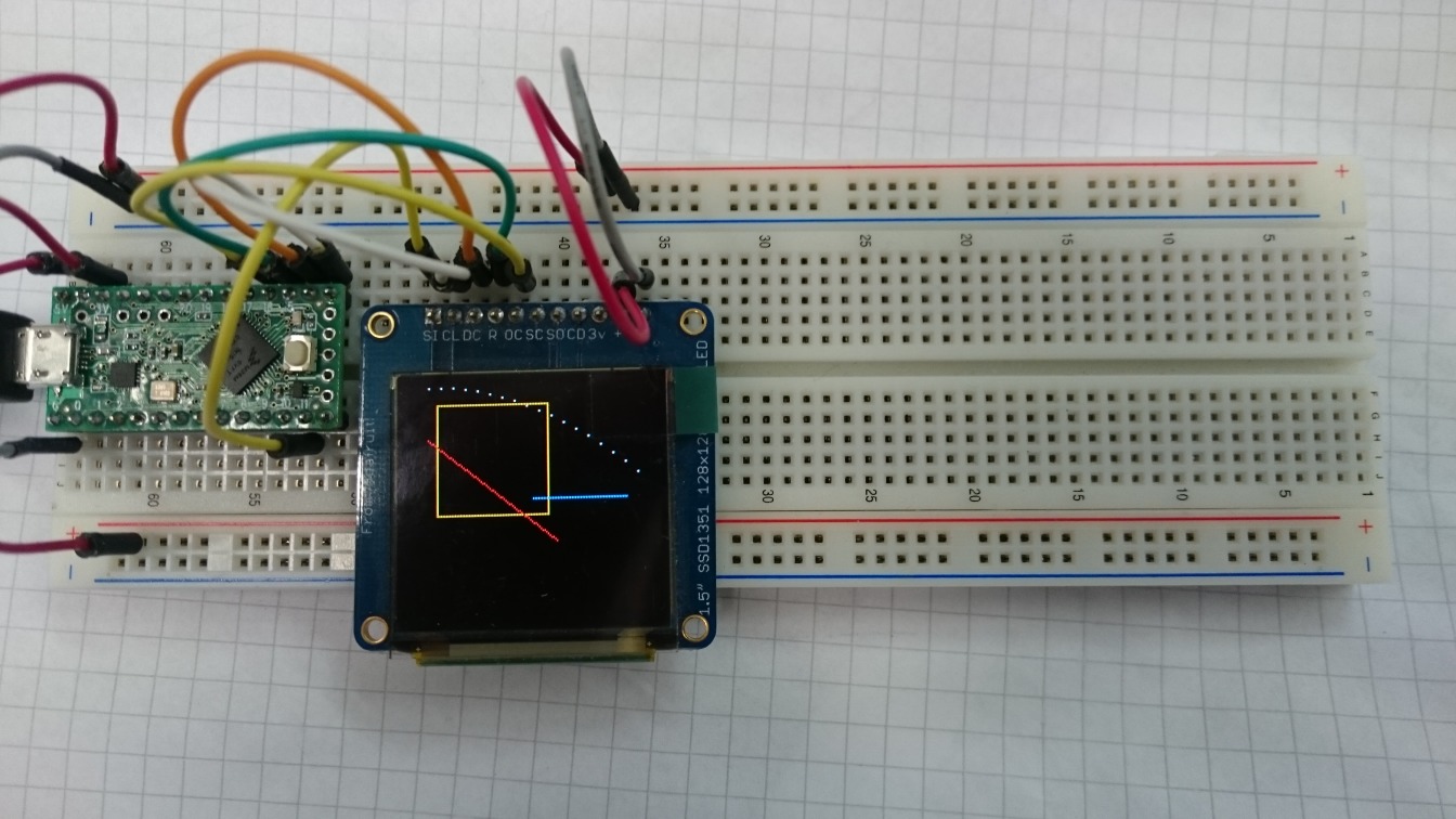
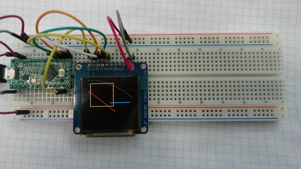
Does the output shown in the attached picture match these commands with height = width = 128? I'm not yet too familiar with the geometry arguments for the various drawing functions so I thought I might ask... // Get the screen size width = gdispGetWidth(); height = gdispGetHeight(); // Code Here gdispDrawBox(10, 10, width/2, height/2, Yellow); gdispFillArea(width/2, height/2, width/2-10, height/2-10, Blue); gdispDrawLine(5, 30, width-50, height-40, Red); for(i = 5, j = 0; i < width && j < height; i += 7, j += i/20) gdispDrawPixel(i, j, White);
-
Oooooooh alright! I simply missed the part where the other drivers fill in stuff in the GDisplay struct! Works now with this gdisp_lld_init(): LLDSPEC bool_t gdisp_lld_init(GDisplay *g) { init_board_pins(g); acquire_bus(g); write_cmd(g, SSD1351_SET_COMMAND_LOCK); write_data(g, 0x12); // unlock OLED driver IC write_cmd(g, SSD1351_SET_COMMAND_LOCK); write_data(g, 0xB1); // make commands A1, B1, B3, BB, BE, C1 accesible in unlocked state write_cmd(g, SSD1351_SET_SLEEP_ON); write_cmd(g, SSD1351_CLOCKDIV_OSCFREQ); write_data(g, 0xF1); // Osc = 0xF; div = 2 write_cmd(g, SSD1351_SET_MUX_RATIO); write_data(g, 127); write_cmd(g, SSD1351_SET_REMAP); write_data(g, 0b01110100); // [0] : address increment (0: horizontal, 1: vertical, reset 0) // [1] : column remap (0: 0..127, 1: 127..0, reset 0) // [2] : color remap (0: A->B->C, 1: C->B->A, reset 0) // [3] : reserved // [4] : column scan direction (0: top->down, 1: bottom->up, reset 0) // [5] : odd/even split COM (0: disable, 1: enable, reset 1) // [6..7] : color depth (00,01: 65k, 10: 262k, 11: 262k format 2) write_cmd(g, SSD1351_SET_COLUMN_ADDRESS); write_data(g, 0x00); // start write_data(g, 0x7F); // end write_cmd(g, SSD1351_SET_ROW_ADDRESS); write_data(g, 0x00); // start write_data(g, 0x7F); // end write_cmd(g, SSD1351_SET_DISPLAY_START); write_data(g, 0x00); // 0 write_cmd(g, SSD1351_SET_DISPLAY_OFFSET); write_data(g, 0x00); // 0 write_cmd(g, SSD1351_SET_GPIO); write_data(g, 0x00); // both HiZ, input disabled write_cmd(g, SSD1351_SET_FUNCTION_SELECT); write_data(g, 0x01); // enable internal VDD regulator write_cmd(g, SSD1351_SET_RESET_PRECHARGE); write_data(g, 0x32); // phase 2: 3 DCLKs, phase 1: 5 DCLKs write_cmd(g, SSD1351_SET_VCOMH); write_data(g, 0x05); // 0.82*Vcc write_cmd(g, SSD1351_SET_PRECHARGE); write_data(g, 0x17); // 0.6*Vcc write_cmd(g, SSD1351_SET_DISPLAY_MODE_RESET); write_cmd(g, SSD1351_SET_CONTRAST); write_data(g, 0xC8); write_data(g, 0x80); write_data(g, 0xC8); write_cmd(g, SSD1351_MASTER_CONTRAST_CURRENT_CONTROL); write_data(g, 0x0F); // no change write_cmd(g, SSD1351_SET_VSL); write_data(g, 0xA0); // external VSL write_data(g, 0xB5); // hard value write_data(g, 0x55); // hard value write_cmd(g, SSD1351_SET_SECOND_PRECHARGE); write_data(g, 0x01); // 1 DCLKs write_cmd(g, SSD1351_SET_SLEEP_OFF); write_cmd(g, SSD1351_WRITE_RAM); // clear display uint16_t i = 0; for (i = 0; i < 128*128; i++) { write_data(g, 0x80); write_data(g, 0); } release_bus(g); g->g.Width = GDISP_SCREEN_WIDTH; g->g.Height = GDISP_SCREEN_HEIGHT; g->g.Orientation = GDISP_ROTATE_0; g->g.Powermode = powerOn; g->g.Backlight = GDISP_INITIAL_BACKLIGHT; g->g.Contrast = GDISP_INITIAL_CONTRAST; return TRUE; } I will adapt my C/C++ separation to the model you suggested (I've already seen the commit, thank you!) and report if it works. Thank you! Christoph
-
Added streaming functions to gdisp_lld_ssd1351.c, but that didn't help: #if GDISP_HARDWARE_STREAM_WRITE LLDSPEC void gdisp_lld_write_start(GDisplay* g) { coord_t x = g->p.x; coord_t y = g->p.y; coord_t sx = g->p.cx; coord_t sy = g->p.cy; acquire_bus(g); write_cmd(g, SSD1351_SET_COLUMN_ADDRESS); write_data(g, x); write_data(g, x + sx - 1); write_cmd(g, SSD1351_SET_ROW_ADDRESS); write_data(g, y); write_data(g, y - sy - 1); write_cmd(g, SSD1351_WRITE_RAM); } LLDSPEC void gdisp_lld_write_color(GDisplay* g) { color_t c = g->p.color; write_data(g, c >> 8); write_data(g, c & 0xFF); } LLDSPEC void gdisp_lld_write_stop(GDisplay* g) { release_bus(g); } #endif // GDISP_HARDWARE_STREAM_WRITE Also enabled hardware streaming in gdisp_lld_config.h: #ifndef GDISP_LLD_CONFIG_H #define GDISP_LLD_CONFIG_H #if GFX_USE_GDISP /*===========================================================================*/ /* Driver hardware support. */ /*===========================================================================*/ #define GDISP_HARDWARE_DRAWPIXEL TRUE #define GDISP_HARDWARE_STREAM_WRITE TRUE #define GDISP_LLD_PIXELFORMAT GDISP_PIXELFORMAT_RGB565 #endif /* GFX_USE_GDISP */ #endif // GDISP_LLD_CONFIG_H Also no change when I remove GDISP_HARDWARE_DRAWPIXEL
-
Regarding those static inline functions: I could replace the "normal" (non-static, non-inline) function declarations such as void select(); // defined in board_ssd1351.cpp with wrappers: void board_select(); // defined in board_ssd1351.cpp static inline void select() { board_select(); } but I really can't imagine how on earth can that have a positive effect on the outcome. Testing this with all functions rewritten as above also shows no difference at all.
-
I have put all the higher level commands in gdisp_lld_ssd1351.c, with as many static inline functions in board_ssd1351.h as possible. This seems to match the pattern of the drivers you have in ugfx with the exception of some C++ in board_ssd1351.cpp. I can not include the main Arduino in board_ssd1351.h, because then the compiler complains about conflicting types for the standard int types (uint32_t). I don't know what exact parts of the libraries (ugfx and arduino) are fighting here... this is the reason why there is no low level I/O in the board header. However, my gdisp_lld_init() is called by ugfx, I can see the output on my terminal. This means that the C++ part of that function works correctly. However, I still don't get any pixels drawn by gdisp_lld_draw_pixel(). It should also show debugging output just to be sure, bot nothing - neither on the display nor on the terminal. Is it possible that some default (empty) implementation of gdisp_lld_draw_pixel() is used by ugfx? gfxconf.h: #ifndef _GFXCONF_H #define _GFXCONF_H #define GFX_USE_OS_RAW32 TRUE #define GFX_NO_OS_INIT TRUE #define GFX_USE_GDISP TRUE #endif /* _GFXCONF_H */ gdisp_lld_config.h: #ifndef GDISP_LLD_CONFIG_H #define GDISP_LLD_CONFIG_H #if GFX_USE_GDISP /*===========================================================================*/ /* Driver hardware support. */ /*===========================================================================*/ #define GDISP_HARDWARE_DRAWPIXEL TRUE #define GDISP_LLD_PIXELFORMAT GDISP_PIXELFORMAT_RGB565 #endif /* GFX_USE_GDISP */ #endif // GDISP_LLD_CONFIG_H gdisp_lld_ssd1351.c: #include #if GFX_USE_GDISP #define GDISP_DRIVER_VMT GDISPVMT_SSD1351 #include "gdisp_lld_config.h" #include "src/gdisp/gdisp_driver.h" #include "board_ssd1351.h" /*===========================================================================*/ /* Driver local definitions. */ /*===========================================================================*/ #ifndef GDISP_SCREEN_HEIGHT #define GDISP_SCREEN_HEIGHT 128 #endif #ifndef GDISP_SCREEN_WIDTH #define GDISP_SCREEN_WIDTH 128 #endif #ifndef GDISP_INITIAL_CONTRAST #define GDISP_INITIAL_CONTRAST 100 #endif #ifndef GDISP_INITIAL_BACKLIGHT #define GDISP_INITIAL_BACKLIGHT 100 #endif #define GDISP_FLG_NEEDFLUSH (GDISP_FLG_DRIVER<<0) /*===========================================================================*/ /* Driver local functions. */ /*===========================================================================*/ // none /*===========================================================================*/ /* Driver exported functions. */ /*===========================================================================*/ LLDSPEC bool_t gdisp_lld_init(GDisplay *g) { init_board_pins(g); acquire_bus(g); write_cmd(g, 0xFD); // set command lock write_data(g, 0x12); // unlock OLED driver IC write_cmd(g, 0xFD); // set command lock write_data(g, 0xB1); // make commands A1, B1, B3, BB, BE, C1 accesible in unlocked state write_cmd(g, 0xAE); // sleep mode ON (display off) write_cmd(g, 0xB3); // Front clock divider / osc freq write_data(g, 0xF1); // Osc = 0xF; div = 2 write_cmd(g, 0xCA); // set MUX ratio write_data(g, 127); write_cmd(g, 0xA0); // Set re-map / color depth write_data(g, 0b01110100); // [0] : address increment (0: horizontal, 1: vertical, reset 0) // [1] : column remap (0: 0..127, 1: 127..0, reset 0) // [2] : color remap (0: A->B->C, 1: C->B->A, reset 0) // [3] : reserved // [4] : column scan direction (0: top->down, 1: bottom->up, reset 0) // [5] : odd/even split COM (0: disable, 1: enable, reset 1) // [6..7] : color depth (00,01: 65k, 10: 262k, 11: 262k format 2) write_cmd(g, 0x15); // Set Column address write_data(g, 0x00); // start write_data(g, 0x7F); // end write_cmd(g, 0x75); // set row address write_data(g, 0x00); // start write_data(g, 0x7F); // end write_cmd(g, 0xA1); // set display start line write_data(g, 0x00); // 0 write_cmd(g, 0xA2); // set display offset write_data(g, 0x00); // 0 write_cmd(g, 0xB5); // set GPIO write_data(g, 0x00); // both HiZ, input disabled write_cmd(g, 0xAB); // function select write_data(g, 0x01); // enable internal VDD regulator write_cmd(g, 0xB1); // set reset / pre-charge period write_data(g, 0x32); // phase 2: 3 DCLKs, phase 1: 5 DCLKs write_cmd(g, 0xBE); // set VComH voltage write_data(g, 0x05); // 0.82*Vcc write_cmd(g, 0xBB); // set pre-charge voltage write_data(g, 0x17); // 0.6*Vcc write_cmd(g, 0xA6); // set display mode: reset to normal display write_cmd(g, 0xC1); // set contrast current for A,B,C write_data(g, 0xC8); write_data(g, 0x80); write_data(g, 0xC8); write_cmd(g, 0xC7); // master contrast current control write_data(g, 0x0F); // no change write_cmd(g, 0xB4); // set segment low voltage write_data(g, 0xA0); // external VSL write_data(g, 0xB5); // hard value write_data(g, 0x55); // hard value write_cmd(g, 0xB6); // set second pre-charge period write_data(g, 0x01); // 1 DCLKs write_cmd(g, 0xAF); // sleep mode OFF (display on) write_cmd(g, 0x5C); // write to RAM // clear display uint16_t i = 0; for (i = 0; i < 128*128; i++) { write_data(g, 0); write_data(g, 0); } release_bus(g); return TRUE; } #if GDISP_HARDWARE_DRAWPIXEL LLDSPEC void gdisp_lld_draw_pixel(GDisplay *g) { coord_t x = g->p.x; coord_t y = g->p.y; color_t c = g->p.color; print_draw_pixel(x, y, c); // debugging output acquire_bus(g); write_cmd(g, SSD1351_SET_COLUMN_ADDRESS); write_data(g, x); write_data(g, 127); write_cmd(g, SSD1351_SET_ROW_ADDRESS); write_data(g, y); write_data(g, 127); write_cmd(g, SSD1351_WRITE_RAM); write_data(g, c >> 8); write_data(g, c & 0xFF); release_bus(g); } #endif // GDISP_HARDWARE_DRAWPIXEL #endif // GFX_USE_GDISP board_ssd1351.h: #ifndef BOARD_SSD1351_H #define BOARD_SSD1351_H #include "ssd1351.h" // pin numbers #define SSD1351_DC 14 #define SSD1351_R 15 #define SSD1351_CS 16 #ifdef __cplusplus extern "C" { #endif // __cplusplus void select(); void deselect(); void command(); void data(); void init_board_pins(GDisplay* g); void acquire_bus(GDisplay *g); void release_bus(GDisplay *g); void write_cmd(GDisplay *g, uint8_t cmd); void write_data(GDisplay *g, uint8_t data); static inline void post_init_board(GDisplay *g) { (void) g; } void print_draw_pixel(coord_t x, coord_t y, color_t c); // for debugging output #ifdef __cplusplus } #endif // __cplusplus #endif // BOARD_SSD1351_H board_ssd1351.cpp: #include #include #include #include "board_ssd1351.h" static SPISettings settings(12000000, MSBFIRST, SPI_MODE0); static inline void setpin_reset(GDisplay *g, bool_t state) { (void) g; (void) state; if(state) { digitalWriteFast(SSD1351_R, 0); } else { digitalWriteFast(SSD1351_R, 1); } } void select() { digitalWriteFast(SSD1351_CS, 0); } void deselect() { digitalWriteFast(SSD1351_CS, 1); } void command() { digitalWriteFast(SSD1351_DC, 0); } void data() { digitalWriteFast(SSD1351_DC, 1); } void init_board_pins(GDisplay* g) { Serial.println("board init"); pinMode(SSD1351_R, OUTPUT); setpin_reset(g, TRUE); pinMode(SSD1351_CS, OUTPUT); deselect(); pinMode(SSD1351_DC, OUTPUT); delay(50); setpin_reset(g, FALSE); delay(50); } void acquire_bus(GDisplay *g) { SPI.beginTransaction(settings); select(); (void) g; } void release_bus(GDisplay *g) { deselect(); SPI.endTransaction(); (void) g; } void write_cmd(GDisplay *g, uint8_t cmd) { (void) g; (void) cmd; command(); SPI.transfer(cmd); data(); } void write_data(GDisplay *g, uint8_t data) { SPI.transfer(data); } void write_data(GDisplay *g, const uint8_t* data, uint16_t length) { (void) g; (void) data; (void) length; for (uint8_t i = 0; i < length; i++) while(length) { SPI.transfer(data[i]); } } void print_draw_pixel(coord_t x, coord_t y, color_t c) { Serial.printf("pixel @ %d %d : %4x\n", x, y, c); } ssd1351.h (not really used yet): #ifndef SSD1351_H #define SSD1351_H #define SSD1351_SET_COLUMN_ADDRESS 0x15 #define SSD1351_SET_ROW_ADDRESS 0x75 #define SSD1351_WRITE_RAM 0x5C #define SSD1351_READ_RAM 0x5D #define SSD1351_SET_REMAP 0xA0 #define SSD1351_SET_DISPLAY_START 0xA1 #define SSD1351_SET_DISPLAY_OFFSET 0xA2 #define SSD1351_SET_DISPLAY_MODE_ALL_OFF 0xA4 #define SSD1351_SET_DISPLAY_MODE_ALL_ON 0xA5 #define SSD1351_SET_DISPLAY_MODE_RESET 0xA6 #define SSD1351_SET_DISPLAY_MODE_INVERT 0xA7 #define SSD1351_SET_FUNCTION_SELECT 0xAB #define SSD1351_SET_SLEEP_ON 0xAE #define SSD1351_SET_SLEEP_OFF 0xAF #define SSD1351_SET_RESET_PRECHARGE 0xB1 #define SSD1351_DISPLAY_ENHANCEMENT 0xB2 #define SSD1351_CLOCKDIV_OSCFREQ 0xB3 #define SSD1351_SET_VSL 0xB4 #define SSD1351_SET_GPIO 0xB5 #define SSD1351_SET_SECOND_PRECHARGE 0xB6 #define SSD1351_LUT_GRAYSCALE 0xB8 #define SSD1351_USE_BUILTIN_LUT 0xB9 #define SSD1351_SET_PRECHARGE 0xBB #define SSD1351_SET_VCOMH 0xBE #define SSD1351_SET_CONTRAST 0xC1 #define SSD1351_MASTER_CONTRAST_CURRENT_CONTROL 0xC7 #define SSD1351_SET_MUX_RATIO 0xCA #define SSD1351_SET_COMMAND_LOCK 0xFD #endif // SSD1351_H I really have the impression that some empty pixel drawing routine is picked over mine; yet when I comment it out, the linker complains about it being missing.
-
Hm...I'm currently rewriting my board_ssd1351.h to contain static inline functions. This is a header included by the C compiler. My low-level interfacing contains C++ calls, and I really don't fancy rewriting tested C++ code in C. So I need to add extern "C" declarations for the C++ leftovers to board_ssd1351.h, which cannot be static inline. The C++ file will then include that header just like it does now. I have the impression that in the end the driver will not call those functions, and the problem remains - just shifted towards a different set of functions. It's also odd that my C++ board_init() function gets called, but the board_drawPixel() does not get called - even though they are in the same compilation unit.
-
Of course, I'll come back with results, whatever sign they might have. Tomorrow should be a good day for that. Thanks for now!