
Joel Bodenmann
-
Posts
2,660 -
Joined
-
Last visited
-
Days Won
2
Content Type
Forums
Store
Downloads
Blogs
Everything posted by Joel Bodenmann
-
The gfxAlloc() function is simply a wrapper macro around pvPortMalloc() if you use the FreeRTOS GOS port. Could you tell us which architecture/platform you're running on? If it's Cortex-M based system, we might be able to get a bit more information out of this by printing out register values etc. in the hardfault handler. FreeRTOS has a resource on this: https://www.freertos.org/Debugging-Hard-Faults-On-Cortex-M-Microcontrollers.html @inmarket Any insights into this?
-
Assuming your image is available via the GFILE module, you can just use the gdispImageXxx() API from here: #include "gfx.h" int main(void) { gImage myImage; // Initialize uGFX and the underlying system gfxInit(); // Set up IO for our image gdispImageOpenFile(&myImage, "my_image.bmp"); gdispImageDraw(&myImage, 0, 0, gdispGetWidth(), gdispGetHeight(), 0, 0); gdispImageClose(&myImage); while(1) { gfxSleepMilliseconds(1000); } return 0; } You can find a ready-to-run demo under /demos/modules/gdisp/images.
-

Inquiry and Updates on ugfx Studio
Joel Bodenmann replied to cheater's topic in Development and Feedback
Hey @cheater - Nice to hear from you again! We're all still looking quite forward being able to have a look at your awesome work! The µGFX-Studio does exist. However, we're currently not handing it out. The plan was to release the first public version together with the v3.0 release of µGFX. After an initial dead blow during the COVID-19 pandemic we got drowned in support requests as everybody was scrambling to migrate their products to whatever silicon was available during the semiconductor shortage and right now we're engaged in larger customer projects. The question of when the µGFX-Studio will be released has therefore become a question of when µGFX v3.0 will be released. Most of the work around µGFX v3.0 has been completed by now. The "only thing left to do" is migrating the higher-level GWIN module to the new GDISP changes as well as updating all examples & documentation. The µGFX library v2.10 is certainly due for a release. You might want to upgrade your application to the latest `master` branch of the git repo to get all the new goodies. Especially the STM32LTDC driver got improved quite a bit. -
One of them is a binary representation of an actual file (Target_whiteBG_20x20.bmp in your case) whereas the other one is most likely raw decoded pixel data. The file2c utility just creates a C array of the binary representation of any file you pipe into it. You'd use its output to include into ROMFS and then draw the actual image via the high-level GDISP API with all the bells and whistles (color conversion, rotation, palette stuff, RLE and so on). Your "LCD image converter" on the other hand provides a raw pixel values tied to a specific format and resolution. Two entirely different things. You don't see an RGB666 option for the LTDC pixel format because that is not supported by the LTDC peripheral found in the STM32F429.
-
The file2c utility simply creates a C array of the byte-content of the file you feed into it. It doesn't perform any conversion. In fact, it doesn't even know whether you feed it a picture, an audio file or an SQL database dump. It just wraps binary data into a C array and adds some entries to use it with ROMFS. If you need to do conversions you'll have to make them before feeding the file through file2c. @inmarket An STM32F4 with LTDC and external SDRAM via FMC can actually handle a 320x240 display with two layers and RGB565. I think it can also handle 320x480. I was working on a project not so long ago with a 480x480 display, dual layer LTDC and RGB565. But yes, this is definitely true: Bandwidth considerations need to be part of the hardware design phase. If your application needs a lot of I/O bandwidth then LTDC can be a real show stopper - especially when paired with SDRAM
-
If you managed to get it working with your PNG approach you'll definitely be able to get it working by directly rendering to a display surface as that is easier (no need to mess with PNG). Instead of writing to a PNG buffer, you'd be iterating the QRcode array the same way but you're directly rendering each QRcode cell to a display surface. This can either be your physical display or a pixmap. The approach should be very simple: Clear the display area which will be occupied by the QRcode using gdispFillArea() For each cell in the QRcode leave it either blank (clear color) or color it in the opposite color as needed using gdispFillArea() Done Given that this is a free public support forum we maintain in our spare time we're usually not able to write actual code for customers. Please feel free to get in touch regarding commercial support if desired.
-
Yes that is a likely cause. The µGFX library will try to write to the memory. It needs to be byte addressable. Usually you'd put the framebuffer in your SDRAM and setting the address(es) accordingly in the board file. You might just as well use the file2c utility that ships as part of the µGFX library in conjunction with ROMFS which allows you to draw pictures from flash all within the cross-platform high-level µGFX API. However, that doesn't resolve the issue that you need to have a writable framebuffer that both LTDC and the CPU (µGFX) can access. That will certainly cause a variety of problems. Just setup your hardware correctly (i.e. RGB565). The µGFX library does not really care tho. It supports a vast number of different pixel/color formats. Both RGB565 and RGB888 are known to work with the STM32LTDC driver. What problem did you encounter? Most likely you're running in the issue mentioned above: When drawing an image using the corresponding GDISP API the µGFX library will load your image (via ROMFS) and then draw that to the framebuffer (either via soft-copy or via DMA2D if enabled and applicable (it has some... restrictions regarding display orientation). Ignoring a lot of details it will basically "copy" your image located in FLASH to the framebuffer as needed. I would generally recommend not to spend time on trying to get stop-gap solutions working and instead making the system work properly as intended by ST. In your case this means having a large enough framebuffer to fit in at least one image (usually two, µGFX supports both a 2nd custom layer as well as built-in double-buffering) and configuring the system accordingly. In any case, it seems like you're almost there!
-
Those settings are specific to yourr display panel. You'd get them from the corresponding datasheet. What exactly do you mean by that? Are you getting a brown-out event? Any high-level example in /demos should work. For board file examples you can have a look at the board files some of the STM32 eval/discovery boards that use LTDC. The STM32F746-Discovery comes to mind. Attached you can find a board file of some custom hardware I was working on recently. The hardware used an ST7701 display controller and the customer insisted on having the display controller configuration in a separate file so the board file simply calls ST7701_Init() and the rest is entirely specific to the LTDC driver. board_STM32LTDC.h
-
The QRcode type contains an array representing a width*width grid of cells making up the QR code. All you have to do is writing a simple function accepting a const pointer to a QRcode and the size of one QR code cell in pixel. Then clear the drawing area (i.e. with white color), iterate over the array/grid and drawing a black rectangle of the specified size for each cell in the QR code that needs to be black.
-
Glad to hear that you got it working! Up to you - I think this thread/topic was not overly specific to either SPI or LTDC.
-
Given that your QRcode object consists of a width-by-width array of 8-bit values for each "pixel", you might just as well render it using gdispFillArea() and bypass all the image non-sense if the QR-Code is not needed for an extended period of time.
-
Yes, that is certainly possible. When it comes to displaying images there are two things to consider: The format/encoding of the image itself. This happens through the GDISP image API. The way you're loading the image. This happens via the GFILE abstraction module. There are plenty of options to choose for both of these points. For the first point, you might translate the QRcode into a NATIVE image format which is easy to achieve as it's the most basic way of representing an image. If you'd like to have more control, you can implement a custom image format wrapping your QRcode object directly. For the second point, you might be able to use the existing MEMFS implementation to load the image from memory. If that is not sufficient, there are provisions for RAMFS. If your underlying system already provides a native filesystem interface with the ability to handle in-memory files you can use NATIVEFS.
-
The µGFX library provides several image decoders and mechanisms to load, decode & draw an image. To get started, you might want to enable ROMFS and use the file2c utility to put an image into your flash. Then display that using the GDISP API to draw the image. You do not (necessarily) need any 3rd-party tooling for this. See: https://wiki.ugfx.io/index.php/Images https://wiki.ugfx.io/index.php/GFILE https://wiki.ugfx.io/index.php/ROMFS Examples are available too.
-
Hello & Welcome to the µGFX community! Unfortunately, we're unable to help at all without being given some information. If you are able to draw rectangles, lines, circles and so on you definitely have the "hard part" done. Most likely you're just missing the correct configuration settings. Check the documentation or provide more information
-
We'll of course also gladly continue answering any questions you might have here
-
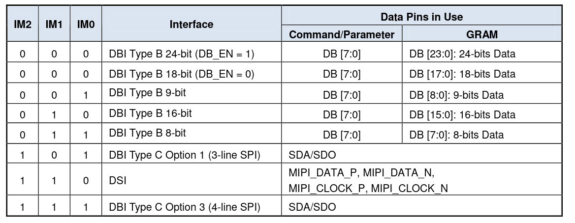
An STM32F4x9 with an ILI9488 configured in 3-wire SPI is probably the worst combination you can have. The STM32 peripheral doesn't provide 9-bit mode so you would have to bit-bang it which is very slow (and eats up all your CPU). Never the less, you can get it to work if that is all you desire. Otherwise, either use the ILI9488 in 4-wire SPI mode or set it to RGB parallel mode and use the LTDC peripheral - that is what it has been designed for. Most of these display modules have simple solder bridges / jumpers for the IM configuration pins. They are rarely "backed into the PCB" if you buy them from a reasonable vendor. Check the module you have. Maybe you can just reconfigure it with a simple solder job yourself without having to make a different purchase. If none of that is an option, and you really just want to get something to show up on the display, I think your only option is to bit-bang the interface as @inmarket mentioned. The point of those IM configuration pins is to select the correct hardware logic (inside of the chip) to talk the interface/protocol you specify. As the same physical pins are shared for different interface options the hardware needs to know which interface it should expect on those pins to setup the correct state machine, command decoder and probably a bunch of other things. Think of these IM pins as being similar to the LSB address pins of some I2C slaves: It's a permanent setting within your finished hardware/device but it's still different between different devices. Therefore, while those can be hard wired on your particular hardware they still need to be configurable. The table from the datasheet illustrates this: Just as a disclaimer: Personally, I have not all the details of the ILI9488 in my memory. However, the ILIxxxx chips tend to all work in similar fashions. But be sure to check the datasheet. Nah, that was just a long shot in case you would have gotten everything else right and the IM pins are configured for the RGB parallel interface. If we may ask: Is this a hobby project? We do offer commercial/paid support where we directly work with customer's hardware to get things up and running. It's sort of our daily bread-and-butter.

-
The IM pins only select the interface for the actual pixel data. Usually the physical display controller (ILI9488 in your case) will always listen for incoming commands on the SPI bus even after you started piping pixel data through a different interface. There are "things" you cannot do via the pixel interface such as changing contrast, gamma correction, backlight settings etc. If your display module is setup to expect pixel data via a parallel RGB interface (i.e. driver via LTDC) it will most likely definitely not react to any pixel data arriving via SPI. Obviously we have very little information on your situation but personally I'd recommend to just get LTDC up and running if your hardware is already designed for that anyway. Be sure to use the latest master branch from the µGFX git repository when using LTDC. We improved the LTDC driver since the last v2.9 release. If you're really desperate you could force the MSB of one of the colors (eg. blue) to high (or low) and check whether the display picks that up. Then you'd at least know whether everything is working
-
Getting compilation error while using gdispPixmapCreate
Joel Bodenmann replied to Vikash's topic in Support
Glad to hear that! -
STM32F429 indeed doesn't have 9-bit mode if I recall correctly. The STM32429i-Discovery and STM32F439i-Eval kits both use an STM32F4xx9 and an ILIxxxx controller connected via SPI (and then LTDC for pixel data). Those have the D/C pin hooked up to a separate GPIO if I'm not mistaken (at least a quick look at the ChibiOS example board files for those boards in the µGFX repository seems to confirm that). As long as you're seeing just a white screen initialization might not have completed successfully (which would again indicate either an incorrectly setup SPI or incorrect initialization sequence). There's not really a point in messing with pixel/color values. If the values are wrong you'll still see something changing on the display, it might just be incorrect colors but it won't stay completely white all the time. Just set it to RGB565 as that is the most common format and make it work with that first. If the GDISP display driver is written somewhat correctly you really shouldn't have to modify any of gdisp_lld_xxx() functions in there unless you want to add features (or change the initialization sequence). I would recommend you to first of all properly verify that the signals on the SPI bus are actually correct (i.e. hook up a logic analzyer or oscilloscope and make sure that the waveforms are correct and look for the correct bytes written out by gdisp_lld_init()). Also make sure that other SPI configuration aspects are correct such as CPOL and CPHA settings. Also note that the ILIxxxx family of controller usually have a lower max SPI bus frequency for initialization/configuration compared to the actual pixel data stream once it is set up. That is what the post_init() function in the board file is usually there for (to change the SPI bus frequency). For now, just make sure that you have a low enough frequency until the thing actually works. You'll need to do verify this no matter whether you'll be piping out pixel data via SPI or via LTDC. SPI is always needed to initialize the display controller. Don't forget to compare the initialization sequence (in gdisp_lld_xxx()) with what your display module manufacturer provided you with. If they flipped the panel or something the configuration needs to reflect that (i.e. remapping pages/segments).
-
Getting compilation error while using gdispPixmapCreate
Joel Bodenmann replied to Vikash's topic in Support
@Vikash Did the CMake integration work out for you? -
@PaulyLV Did you manage to get it working?
-
That is the fallback implementation if the underlying system doesn't provide any better means of filling a whole area with a solid color. If you look at the full implementation you'll notice that whenever possible we use hardware accelerated clearing, if that is not available we'd use hardware accelerated area filling, if that is not available we use color streaming and if that is not available the only option left is setting each pixel individually. The ILI9488 driver that ships with the library implements stream based access which means that we can setup a window and then stream each pixel value without addressing it individually. You'd certainly get a lot more performance on these things when using LTDC as it supports hardware acceleration (via DMA2D) which is implemented in the corresponding µGFX driver here. Have you checked whether that matches the implementation of gdisp_lld_init() here? Yes, that's correct. The LTDC interface is only there to stream the actual pixel/color values. You still need a side channel to actually initialize & configure the display controller (ILI9488). A good start would be to probe the bus and checking whether there is any activity at all. There's little benefit in checking the correct initialization sequence/parameters if you don't know whether the data actually appears on the physical bus correctly. Some of the drivers that ship with the µGFX library have been contributed by community members (something we'll be separating for the next major release). I haven't checked the details but most likely the board file would ask you to acquire the bus (i.e. handle mutual exclusion on the HAL layer and setting CS low) and then simply call write_index() / write_data() for as many times as necessary. The driver will then ask you release the bus once it's done. It's also possible to extend the board file to use DMA if needed but generally you'd want to go LTDC anyway if that was your original plan.
-
Getting compilation error while using gdispPixmapCreate
Joel Bodenmann replied to Vikash's topic in Support
If you're using the current master branch of the v2 git repository you can use the built-in CMake integration. This way you can integrate the µGFX library into your CMake project the same way you'd integrate any other library shipping with a CMake find module. Add FindUgfx.cmake to CMAKE_MODULE_PATH: list(APPEND CMAKE_MODULE_PATH /path/to/ugfx/cmake) Include via find_package(): find_package( ugfx REQUIRED COMPONENTS drivers/gdisp/SSD1312 ) Link target: target_link_libraries( ${TARGET} PRIVATE ugfx ) Note that not all drivers have received the corresponding driver.cmake file yet which is why µGFX 2.10 has not been released yet. However, you can easily add them yourself (or you can let me know and I'll add it for you). -
Hello & Welcome to the µGFX community! I currently don't have time to look at the files you shared in detail but a few hints: There is a bit of a history of issues with the ILIxxxx display controllers. There are quite a few knock-offs / clones and worst: Different silicon revisions that have different initialization sequences and the display module vendor doesn't tell you about it as the part name is literally the same. Did you get an initialization sequence from your module manufacturer/vendor? If so, try to replace that in gdisp_lld_ILI9488.c. This is basically the place where all the configuration happens. µGFX v3.0 has a nicer interface to do this without modifying the driver itself but we're not there yet. If I remember correctly the ILI9488 driver that ships with the µGFX repository is by default setup for RGB565. Other color formats should work, but might require a different display controller initialization sequence/parameters (as described above). For the sake of testing, I'd try switching to RGB565 temporarily. Have you probed your SPI bus? Does what you see match expectations? You mentioned that you re-use a project that previously used a different display controller: Any chance that there is a stray setting for the color format somewhere? I.e. in your build system or the gfxconf.h configuration file? Technically you shouldn't have to touch this to just use the µGFX library - especially if you can use an existing driver. If an existing driver is suitable you only need to implement the board file. Even if you need to implement your own driver the µGFX GDISP core will handle color conversions for you. That is actually why the driver config file has a setting for the low-level pixel format (i.e. the format the display controller expects). For debugging you can disable both GDISP_HARDWARE_STREAM_WRITE and GDISP_HARDWARE_STREAM_READ if the situation requires so but generally you want to use those in case of the ILI9488 driver. If streaming is disabled, each pixel needs to be addressed individually which adds a lot of overhead especially on the SPI bus.
-
Getting compilation error while using gdispPixmapCreate
Joel Bodenmann replied to Vikash's topic in Support
You seem to be using the single-file-inclusion mechanism. Pretty much the only draw-back of using that mechanism is that multiple displays and pixmaps don't work as stated in the documentation: https://wiki.ugfx.io/index.php/Getting_Started#Single_File_Inclusion If you want to use pixmaps you can either directly use the Make or CMake files or manually add the µGFX source files to your existing build system.