PaulyLV
-
Posts
17 -
Joined
-
Last visited
-
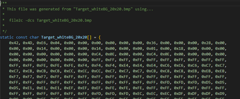
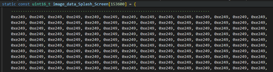
Here are snippets of the C files generated using file2c utility and LCD image converter (specified RGB565 format). I don't understand how both these arrays would generate the same result when used as the framebuffer address in LTDC. Sorry that the snippets I included are actually two different images so they will not generate the same result, but I hope you understand what I am trying to ask. Does the 8-bit vs 16-bit data format not matter?
-
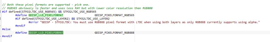
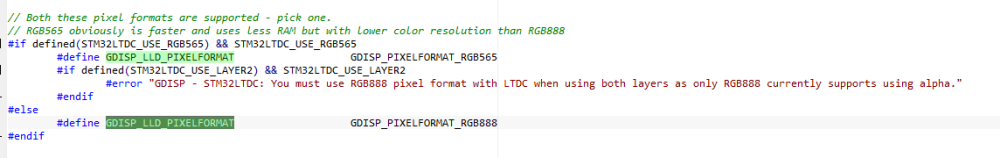
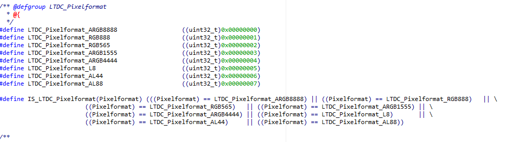
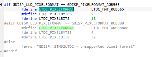
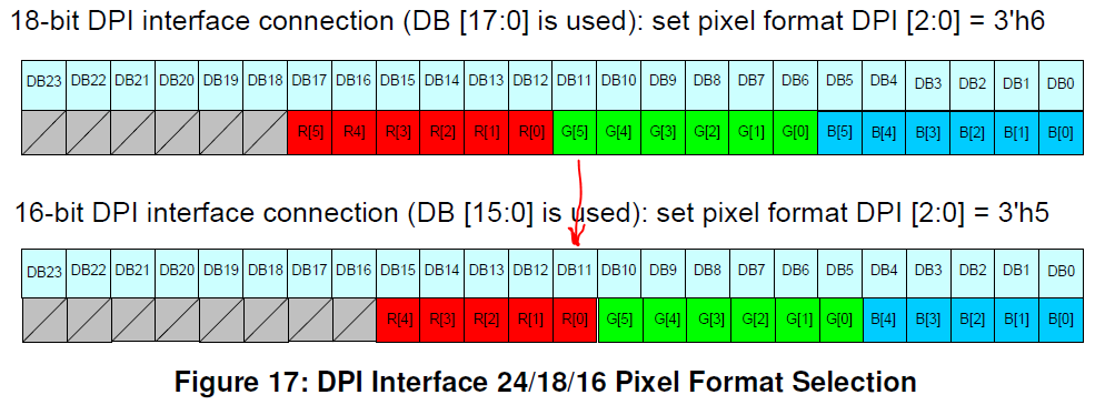
Yes, I am definitely not understanding something. I would like to use 18-bit DPI interface with LTDC. According to the LTDC application note, it is possible. But, in the gdisp_lld_config.h file included in the STM32LTDC folder in uGFX, the pixel formats mentioned are only RGB565 and RGB888. Second, in "stm32f4xx_ltdc.h", RGB666 is not listed as a pixel format. Third, in "gdisp_lld_STM32LTDC.c", only two pixel formats are available. Are you saying that the pixel format specified in these files is not related to the DPI interface but is the framebuffer format? How does the LTDC peripheral "know" that I want the RGB666/18-bit DPI format then? What am I missing?
-
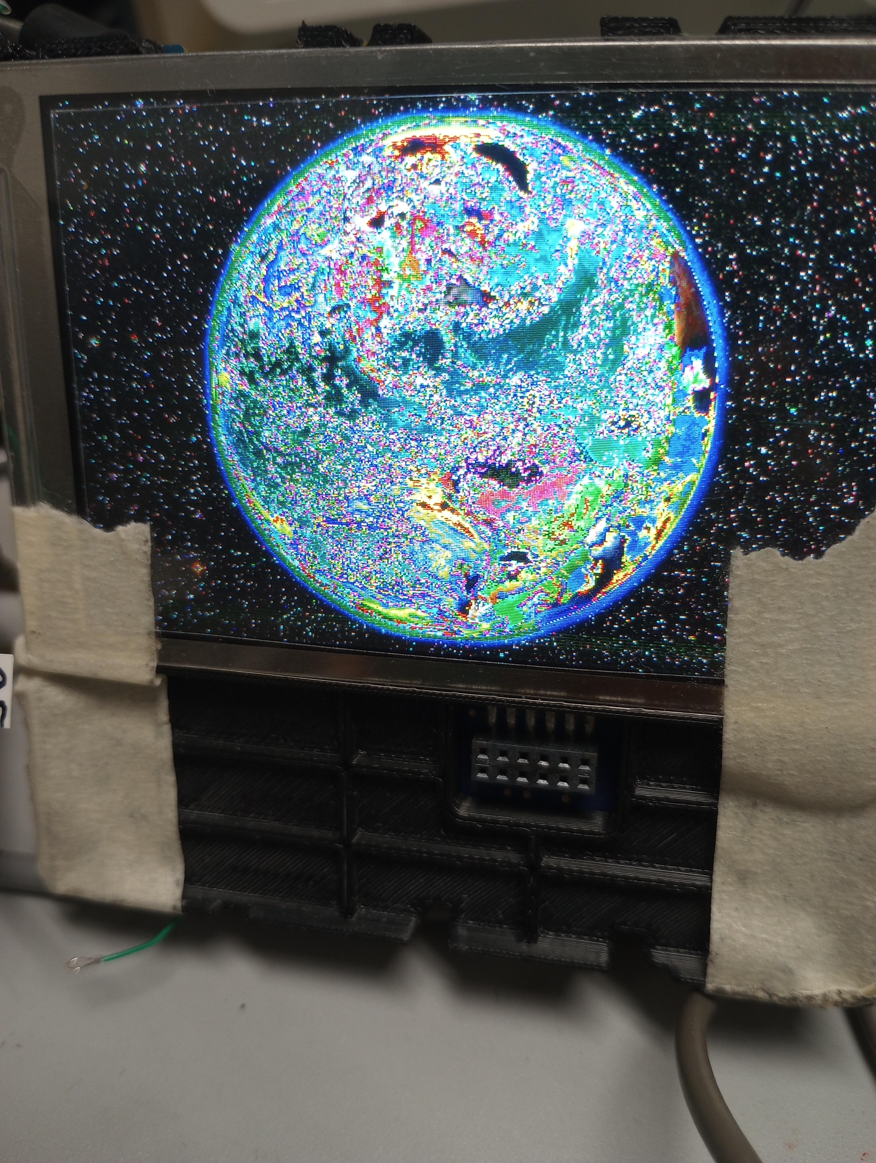
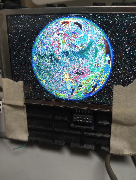
I definitely feel a step closer. I set up a smaller array in RAM and was able to display information that our product is supposed to display. The current design does not have SDRAM on it. Still trying to make a case that we need it. The requirement is to only update a certain process value on the screen each time but, as far as I can tell, LTDC will update the entire frame each time, correct? Even if I set up two layers, with the second layer only updating the process value I still need the minimum amount of RAM for one full frame (320 x 480 x 2bytes per pixel). I think the colors are messed up due to the hardware but since that is on the PCB I will have to wait for the next iteration of the board to check that. Is there a way to specify the pixel format in the 'file2c' utility? I ended up using the 'LCD image converter' which was actually working ok once I realized that it was the hardware that needs to be updated.
-
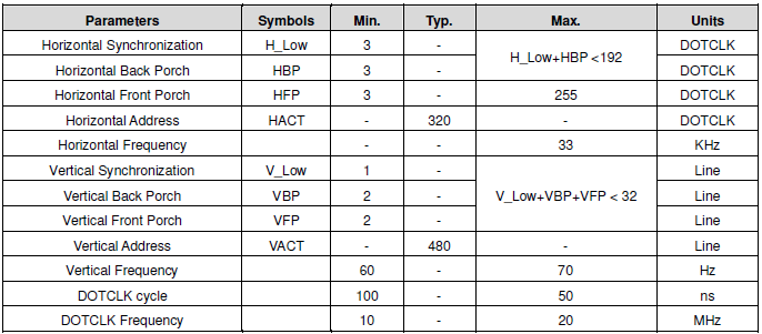
I commented out the gdisp_lld_draw_pixel function. This has stopped the microcontroller from resetting as soon as LTDC is enabled. The reset is from an exception frame. I wonder if has to do with the frame buffer address being that of an array stored in flash. I will need to look into that some more but for now I am trying to display an image to check if LTDC is working. I am using a header file for an image that I generated using a program called 'LCD_Image_converter' that I found online. I am able to display something with LTDC but it is not the right color and the resolution is really bad. My timing parameters are all within the range specified by the LCD datasheet. I am using the RGB565 pixel format but my hardware is connected for RGB666. I chose RGB565 since LTDC does not support RGB666. Could this be the reason I am getting such a pixelated image with wrong colors? Is the issue with the header file I am generating for the LCD? I tried using file2c program in uGFX and had less success. Any help you can provide is appreciated. HBP 4, HFP - 10, VBP - 2, VFP - 2 ( suggested by field engineer) H_Low - 41, V_Low - 10 (from IAR example for LTDC) LCDCLK freq - 12 MHz, HSync - 32 kHz, VSync - 64 Hz World480x320.BMP
-
I got the latest uGFX STM32LTDC functions and I set up LTDC with the following - single layer, pixel format RGB565, edited the width and height for ILI9488 but left the front porch, back porch settings as is. After I enable LTDC, I can see the HSYNC and VSYNC signals. The microcontroller resets during the call to gDispClear. I enabled the interrupt but I'm not really sure what needs to happen in the interrupt service handler. Are there any examples using uGFX STM32LTDC you could recommend? Not sure if the incomplete interrupt handler is causing the reset.
-
I am working on the LTDC portion now. Should I start a new topic, or can I continue to ask questions on this one?
-
I have an update. My teammate was able to get colors to display on the screen using the SPI interface. The initialization sequence had to be tweaked as well as the gdisp_lld_write_color function to use RGB666 pixel format. I will attach the initialization sequence in case it helps someone else using this LCD screen in the future. LLDSPEC void gdisp_lld_write_color(GDisplay *g) { // write_data(g, gdispColor2Native(g->p.color)); write_data(g, (gU8)((gdispColor2Native(g->p.color) & 0x0003F000) >> 10)); write_data(g, (gU8)((gdispColor2Native(g->p.color) & 0x00000FC0) >> 4)); write_data(g, (gU8)((gdispColor2Native(g->p.color) & 0x0000003F) << 2)); } gdisp_lld_init_ILI9488.txt
-
Not a hobby project. I will let you know if we need paid support. Thank you for taking the time to respond to my questions.
-
The field engineer says that the IM pins on my LCD sample are hardwired for a 3-wire serial interface. If what he is saying is right, then all LCDs that need SPI initialization would ship with IM pins set to SPI interface. Then what is the point of having various settings for IM pins. This makes no sense to me. I am suspicious of the initialization code as well. Oddly enough, the 'All pixels on' command only works when the 'Display Function control'(B6h) command is using default parameters. Why one would affect the other is beyond me. I would assume the command should work no matter what your interface as long as the SPI connection is good. I am desperate and willing to try anything to see something other than white on my display. I tried to set all the bits on the "LCD red" pins and don't see anything. Did you mean setup LTDC first and then set the pins high/low?
-
Thank you Joel and inmarket for your responses. Yes, STM32F429 supports only 8-bit and 16-bit SPI. The discovery board uses the 4-line SPI so 8-bit SPI would work since the data/command line is separate as you said and does not need to be transmitted over the SDA line. My teammate was able to get the 'All pixels on' command working with bit-banging SPI so the initialization sequence should be making it out but not able to see any color yet. When placing the order for the LCD, we had requested an 18-bit parallel interface. The status of the IM pins is confusing because if all LCDs need to be initialized using SPI then are the IM pins always set to serial interface? Then, what's the point of having the other configurations mentioned in the datasheet? I am checking with our LCD supplier to confirm the configuration of the IM pins on the LCDs we have. Would it be possible to display color via serial or parallel interface irrespective of the IM pins status based on what the initialization sequence does?
-
I turned on the gfx logo also but I don't see anything on the screen for that either. I guess I don't have the SPI connection working the way it is supposed to be. The white screen baffles me. I would expect blank screen if SPI was not working but I guess something is making it across and the LCD interprets that as all white. There are different brightness levels to the "white screen" if that makes sense. In gfxconf.h #define GFX_USE_OS_RAW32 GFXON #define GFX_OS_HEAP_SIZE 24000 #define GFX_USE_GDISP GFXON #define GDISP_NEED_VALIDATION GFXON #define GDISP_NEED_CIRCLE GFXON #define GDISP_NEED_MULTITHREAD GFXON #define GDISP_NEED_TEXT GFXON #define GDISP_NEED_TEXT_WORDWRAP GFXON #define GDISP_NEED_TEXT_KERNING GFXON #define GDISP_INCLUDE_USER_FONTS GFXON #define GDISP_NEED_IMAGE GFXON #define GDISP_NEED_IMAGE_GIF GFXON #define GDISP_NEED_IMAGE_BMP GFXON #define GDISP_STARTUP_COLOR Black #define GDISP_NEED_STARTUP_LOGO GFXON #define GFX_USE_GWIN GFXON #define GWIN_NEED_GRAPH GFXON #define GFX_USE_GFILE GFXON #define GFILE_NEED_ROMFS GFXON In gdisp_lld_config.h #define GDISP_HARDWARE_STREAM_WRITE GFXON #define GDISP_HARDWARE_CONTROL GFXON #define GDISP_LLD_PIXELFORMAT GDISP_PIXELFORMAT_RGB233
-
If I compile a list of all the settings that are turned on between gfxconf.h and gfx_lld_config.h, maybe something will stand out as incorrect?
-
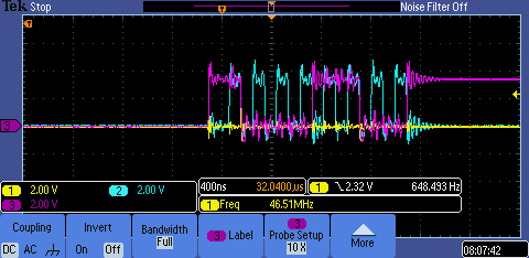
Joel, thank you for your earlier responses and for checking in. Unfortunately, I am still stuck on the flashing white screen. So far, I have tried to use 16-bit SPI since I technically need 9-bit transmission to send the D/C bit. No display. I used the original uGFX initialization routine for ILI9488 with RGB565 pixel format. Still flashing white screen. I changed the pixel format to RGB666 and attempted to send 3 bytes of data by calling write_data 3 times within gdisp_lld_write_color(). This causes the microcontroller to reset. Not good. The project I am using calls gDispClear and gDispFillArea periodically. I think my white screen is coming from these calls but no matter how I change the parameters, I cannot seem to see any colors on the screen. One of the SPI transmissions is in the attached image where the blue represents clock and the pink represents data. There are only 8 clock cycles but 9-bits of data. I wonder if this is what is causing the issue. Another colleague of mine also tried to "bit bang" the SPI interface but he sees a white screen as well. The only available data formats using 3-line SPI on ILI9488 are 8 colors or 262K colors. The current pixel format is set to RGB233.
-
Another question I had In function gDispGClear(), area = 320 X 480, for(; area; area--) gdisp_lld_write_color(g); which means 'write_data' is called for each pixel, right? I would expect to be able to write a color to the screen by writing a value in here but even that does not seem to be working. I feel like I am missing something fundamental about how the interface works.
-
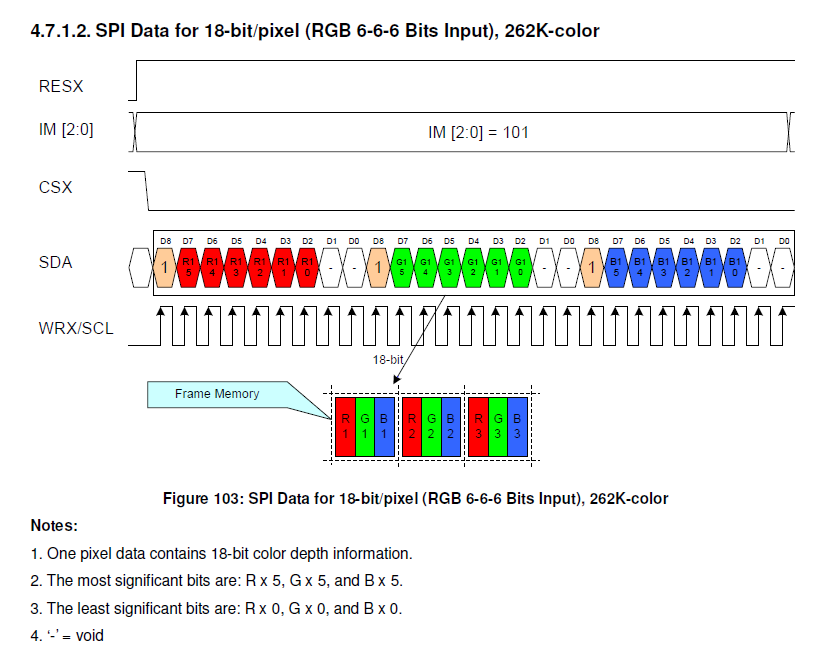
My team purchased the LCD from US Micro and received the initialization sequence from them. The initial plan was to use RGB666 and LTDC but since we ran into some stumbling blocks like not realizing that a SPI connection is required to initialize the LCD in the first place, the LTDC plan was put on hold. For now, the goal is to get the LCD to display some color using SPI. In the initialization sequence, command 3Ah selects the interface and I think it is set to both DPI and DSI. I am not sure what my expectation on the SPI bus should be. Based on the ILI datasheet, SPI data for RGB666 looks like this but does that mean that each write_data() call would actually need to be called 3 times for each pixel which is why I asked about modifying gdisp_lld_write_color() function.