
cpu20
-
Posts
130 -
Joined
-
Last visited
Content Type
Forums
Store
Downloads
Blogs
Everything posted by cpu20
-
Version 1.0.1
864 downloads
An example project for the STM32F469I-discovery board in the AC6 SW4STM32 IDE. As a demo the demos/modules/gwin/button application is used. -
I personally don't think your configuration is wrong, but the problem lies in the gfxSleepMilliseconds used before vTaskStartScheduler is called. FreeRTOS doesn't initialize the scheduler until you explicitly call vTaskStartScheduler. So that means that any call of vTaskDelay before the scheduler is initialized will result in a HardFault (or a hangup). A simple thing you can try to see if this is indeed the problem is to use the HAL_Delay() function again. (Make sure the HAL SysTick is initialized and running by calling HAL_Init and putting the SysTick handler in the stm32fxxx_it.c)
-
I doubt that will work as vTaskStartScheduler never returns. So all the other initialization functions will never execute.
-
Did you correctly add a gdisp driver? They are located at drivers/gdisp. See the adding drivers section at: https://wiki.ugfx.io/index.php/Using_Keil_µVision_5_MDK-ARM for more information on how to add one to your project.
-
Ah yes! It could be that the camera module also uses some color definitions. Normally all these problems will go away with µGFX V3 so that is good news! Setting up a project is indeed the hardest part sometimes! But after setting it up comes all the fun If you have any other problems just let us know!
-
The project doesn't really fix anything. It just doesn't include any files from the HAL-library that have color defines in them that conflict with the µGFX colors. So in that project the DMA2D HAL-component is just not included so it doesn't cause any trouble. So including the DMA2D indeed causes your compile problems. I don't see why you would want to include the DMA2D HAL-module as you are using µGFX to drive the display. What I would recommend: - From the Utilities/STM32F746G-Discovery folder exclude the stm32746g_discovery_lcd.c and .h files. - After that also exclude the DMA2D HAL-component from the build again. Normally that should fix the color problems and you should be able to use µGFX to drive the display and use the other BSP components.
-
@inmarket something is wrong with the uGFX servers. The download page is offline. Also I get the same error message trying to clone the repo. Also when you go to the forums index you can see that you replied to this topic in the Developments and Feedback section. But when clicking on Developments and Feedback it shows that this topic has no replies...
-
I was under the impression that this driver was fixed in the past... In this thread it was discussed that the driver doesn't work and @doc_rob seemed to be able to fix it: Maybe @doc_rob can share the fixed driver?
-
I have never used ARCH before, but after some googling it seems that they don't use dev-packages. Instead the development files are also being installed when you install the basic package. My guess is that you can just install the sdl2 package and it should work.
-
It seems that there is no board file for the ST7735 which is strange. You should however be able to use the board file from the ST7565 and modify it for the ST7735. Just correctly rename the file and remove all the defines at the top. After that you can start implementing the functions for your platform. This could guide you for what each function should do:
-
Two things to start with: - Did you do a clean build? (right click on project->clean) - In the includes did you add the uGFX directory to all languages or only to assembly? If you did add it only for assembly do it for all the other languages too.
-
I've played around with Code::Blocks a bit and got it to successfully compile a project for an STM32 target using single file inclusion. But the build process is fairly complex as you have to set all the compiler and linker flags manually. There is a plugin that does this for you but it's €10 - €20 as it is a third party plugin. I also tried to setup a project to build for Linux (SDL-driver) and that went pretty smooth using the single file inclusion mechanism. That's because a lot less flags have to be set and the configuration overall is easier. But overall I would say that the Makefile approach will be the easiest to set up and maintain when using Code::Blocks.
-
I haven't used Code::Blocks yet, but I will look into it when I got the time. A bit late to the party as you already got it figured out As @Joel Bodenmann said the Makefile approach is the most simple and versatile one. If Code::Blocks can make it's own Makefiles it should be able to use the single file inclusion mechanism but it will be more difficult to set up.
-
The answer to your question is in the wiki. The console does not keep track of it's history and will be emptied when set invisible. You need GWIN_CONSOLE_USE_HISTORY for console history. I have no idea why your application crashes...
-
Be careful with upper and lower case mixing in the llD/lld. The gmouse_lld_FT5x06.c file is already written in present in that folder. Any reason why you are rewriting it? You should only have to write the board file. Is gfx the root folder of the µGFX library? Because you should not inlcude files this way. Normally you include source files and headers files through you IDE or your makefile. This is already defined in the gmouse_lld_FT5x06.c file. You should not redefine it as it will give you errors like the one you are getting now.
-
You are loading the image inside the StartGFXTask. This means that the stack allocated for this task will be used to load the image. In your code you assign 1k for the task, but it is possible that if you are opening a large image it consumes the whole stack of the task. So to begin make the stack of your StartGFXTask bigger.
-
Your application code should always use the functions from the GDISP library. These functions will use your display driver (gdisp_lld_OTA7001A.c ) to send the wanted pixels to the display, and the driver will then call the functions in the board file to actually send the data to the display. For all the functions you can use in your application code you can use the API reference. If there is anything you are uncertain about when writing the driver files, let us know. Always here to help
-
Every implementation that is available is present in boards/base. It seems that for your board there are no baremetal drivers available yet. The only drivers available use ChibiOS. The only option for now will be to write the board files yourself.
-
You left all the board-file functions empty. They are nescessary for communicating with the display.
-
I'll do my best to try and explain most of them. Someone correct me if I'm wrong. init_board: This function is responsible for configuring the peripherals on the MCU that will be used to drive the display. It should configure all the pins in the correct configurations, put them in a defined stat if nescessary (like putting the backlight/reset pins on the LCD in a known state). Also it should intialize the peripherals used to drive the display (like the SPI-peripheral or I2C-peripheral) and make sure all the clock settings are correct for the peripheral to operate. If external memory like SDRam is used to store the framebuffer it should also be initialized here. post_init_board: Anything that needs to happen after the display has been fully initialized should come here. setpin_reset: Set the reset pin in a certain state. set_backlight: Set the backlight to a certain percentage. Most of the displays have a PWM-pin that can be driven to set the backlight. aqcuire_bus: If the display is driven over a bus (like spi) become owner over the bus. In case of SPI lower the chip select (and when using an OS use a mutex) release_bus: Release the ownership when it is no longer needed. setreadmode: Put the display in read mode. setwritemode: Put the display in write mode. read_data: Read data from the display. write_data: Write data to the display. write_index: Send a command to the display.
-
Yes, but this file does not only assign pin functionality, but also provide functions that use the HAL (or you could directly work with the MCU register whatever you prefer) to send commands to the display. Like write_data() and this function will send the data over the SPI interface using the HAL for example. This file will be called board_OTA7001A.h. If you look into the board/base folder there are alot of examples of this. This is the same as for the display. In the drivers/ginput/touch/FT5x06 folder there is a file called gmouse_lld_FT5x06_board_template.h that is used by the FT5x06 driver. This file contains all the function calls needed to communicate with the display. You have to copy this file, rename it to gmouse_lld_FT5x06_board.h and fill in all the functions. Again for examples see boards/base Laslty is the driver itself. This will be a file gdisp_lld_OTA7001A.c which is the actual display driver. This file uses the function calls from the board_OTA7001A.h file to send all the nescessary commands to the display to configure it etc... By using the board file you make an abstraction from the MCU, because the commands which are sent to the display to configure it are always the same. So you will write: write_data(OTA7001A_REG_CONFIG, 0x34) for example an this way the gdisp_lld driver does not need to know how the command will be send to the display. It could send this command over I2C, SPI or anything else depending on how you filled in the board file.
-
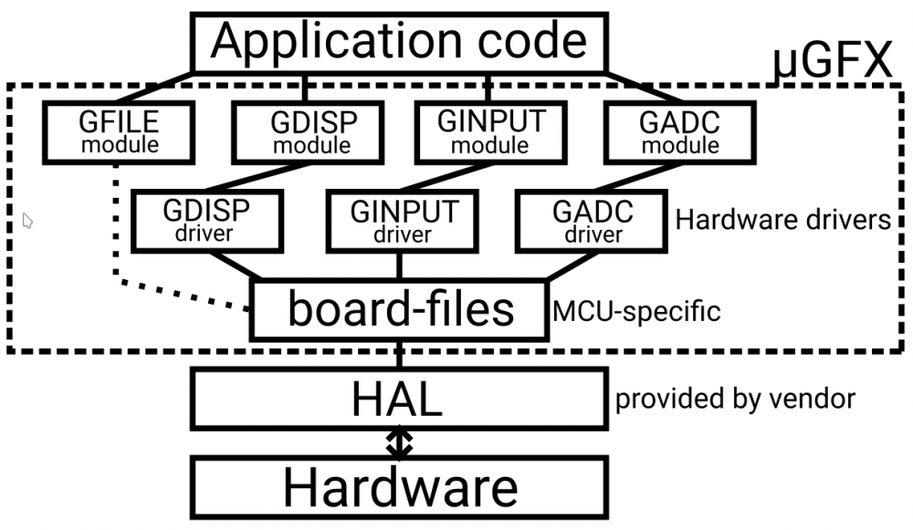
That is indeed true. All the Eclipse based IDE's can just follow the Eclipse/Chibistudio guides. The driver for the display you will use is divided into two parts. There will be a GDISP driver that holds the "high" level logic to drive the display. This will send the right commands to the display, maintain the framebuffer, etc... (see other drivers as examples). The second part is the board-file. This file is the layer between the GDISP driver for the display and the hardware. This file will hold all the functions necessary to send the commands over the hardware interface to the display (I2C, SPI, FMC, ...). This way the driver only has to be written once for that display driver and only the MCU specific interface has to be rewritten. I hope that makes things a bit clearer. Note that this is a very simplified drawing just for illustration. If you have any questions don't hesistate to ask.
-
As @AlexMiron31 mentioned Attolic is Eclipse based, and so it is possible to import projects that are made in Eclipse. You could import this project: and you can set this up for your specific board and LCD. It should be fairly straight forward. Or you can indeed follow the Eclipse guide as it fully applies to Atoolic too.
-
Ok I got your project to compile. First of all: Use the git version of µGFX please!!! There are some error that pop up because you are using an outdated version µGFX. The stm32f746 board files have changed alot since µGFX v2.7. Second problem is as mentioned here: The naming schemes overlap. Just excluding the unused HAL-components fix this already and save you alot of code space. I also added "FATFS USBH_fatfs;" to your main as it was missing. Lastly I had to delete the ffconf.h file from the µGFX root directory as it was trying to used it as the configuration file for the FatFS. If you have any other questions don't hesitate to ask! _f7_disc_usbh.zip
-
Those undefs have never been in the board file as far as I can remember. The reason this conflict does not occur in the example projects is because there (almost) all the unused HAL-components have been disabled to save code space. This also excludes the dma2d from the build and thus not giving any conflicts. Of course the proper way to fix this is to add the undefs to the board file.

