solijoli
-
Posts
5 -
Joined
-
Last visited
-
But when you use PE3 to Command/Data, in my case RS, where do you connect PD11 with? Other than that are the connections same with you? I'am using the codes you sent. There is GFX_NO_DISPLAY_INIT TRUE in the board_SSD1963.h file. I just changed the timings so they should be good for 7 inches. Thanks.
-
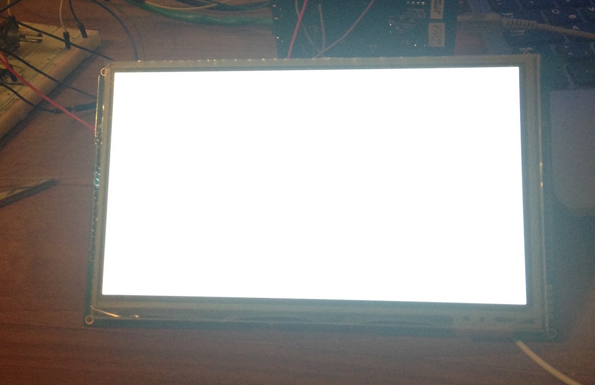
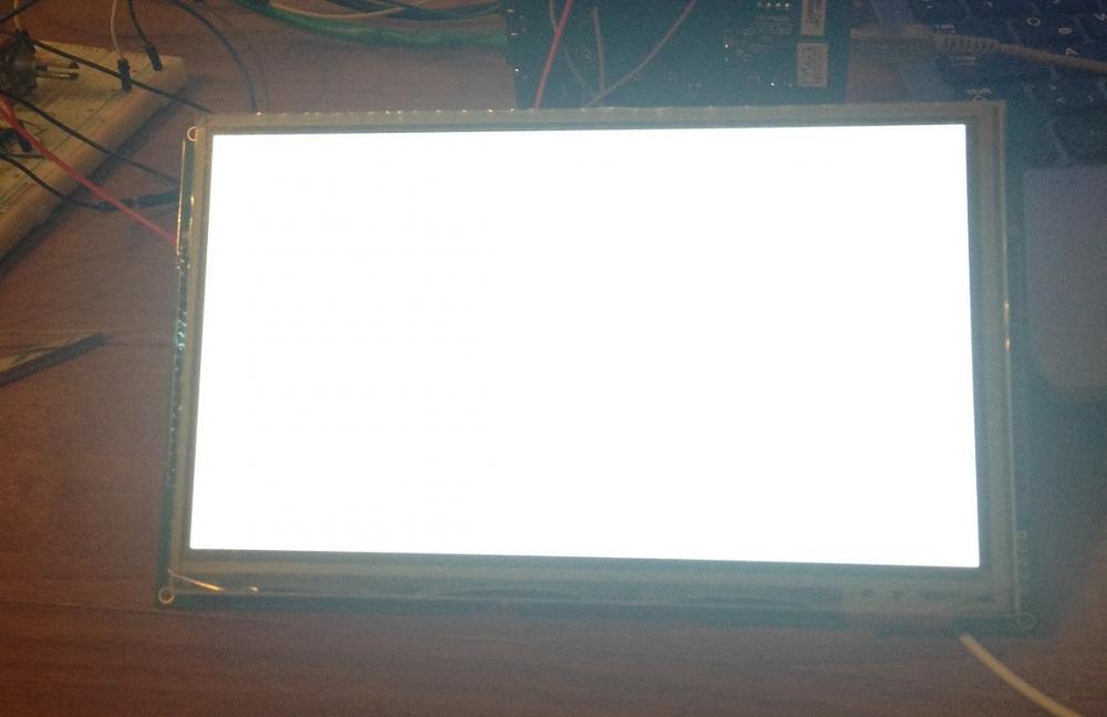
Hello, I managed to build the demo project on eclipse, thanks so much for the help! But now that I uploaded the code on the touch screen, I only see a white screen now like in the picture (before it was worse where there were much noise all over the screen). I've used the DD_Special board the steved had sent but changed GDISP_SCREEN_WIDTH, GDISP_SCREEN_HEIGHT, // Panel width and height 2, 2, 41, // Horizontal Timings (back porch, front porch, pulse) CALC_PERIOD(800,2,2,41), // Total Horizontal Period (calculated from above line) 2, 2, 10, // Vertical Timings (back porch, front porch, pulse) CALC_PERIOD(480,2,2,10), // Total Vertical Period (calculated from above line) CALC_FPR(800,480,2,2,41,2,2,10,60ULL), // FPR - the 60ULL is the frames per second. Note the ULL! 0 // Flags to GDISP_SCREEN_WIDTH, GDISP_SCREEN_HEIGHT, // Panel width and height 46, 210, 41, // Horizontal Timings (back porch, front porch, pulse) CALC_PERIOD(800,46,210,41), // Total Horizontal Period (calculated from above line) 23, 22, 10, // Vertical Timings (back porch, front porch, pulse) CALC_PERIOD(480,23,22,10), // Total Vertical Period (calculated from above line) CALC_FPR(800,480,46,210,41,23,22,10,60ULL), // FPR - the 60ULL is the frames per second. Note the ULL! 0 // Flags and didn't changed the gdisp_lld_SSD1963.c file (Was I supposed to?) In the readme file it said "SD1963 driver modified to handle Displaytech INTXXX displays" I've connected the pins of stm32f4 and the board according to: https://www.google.com/search?q=stm32f4 ... B948%3B521 which is also the same with naftilos76' project and the datasheet, where I have connected all CS, RS, all the grounds except the fields about touch. I have also built a circuit that takes 5 V and creates 3.3 and 1.2 V for the requirements of VDDIO, VDDD, VDDLCD. http://www.mouser.com/ds/2/116/int070at ... 221474.pdf @steved in the board_SSD1963.h file in DD_Special, you use IOBus busD = {GPIOD, (1 << 0) | (1 << 1) | (1 << 4) | (1 << 5) | (1 << 7) | (1 << 8) | (1 << 9) | (1 << 10) | (1 << 14) | (1 << 15), 0}; IOBus busE = {GPIOE, (1 << 3) | (1 << 7) | (1 << 8) | (1 << 9) | (1 << 10) | (1 << 11) | (1 << 12) | (1 << 13) | (1 << 14) | (1 << 15), 0}; Where did PE3 need to connect? In the board.h file it is stated in GPIOE setup section; PE3 - FSMC_DC. I didn't understand what to do with that but I think the problem is probably about the touch screen connections? What can be done about this? Thank you!
-
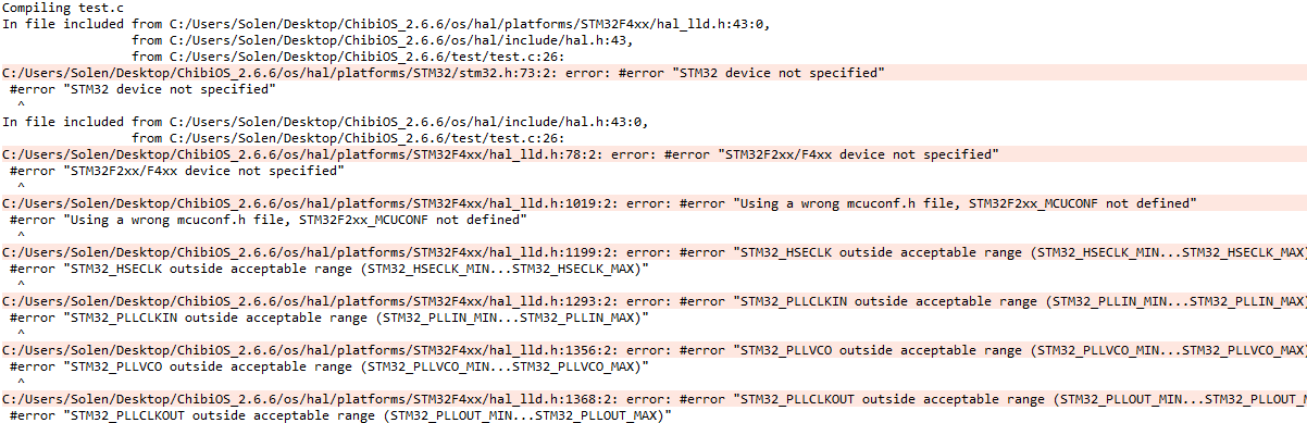
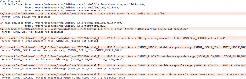
Hello again, I couldn't managed to build the DSO project so I wanted to go back to basics. I downloaded the Chibios 2.6.6 and added the Tectu's ugfx folder inside ext folder. Then on Chibios, I copied the demo for STM32F4 Discovery to a new folder, updated the Makefile and was able to build it, so I don't think there is a problem with Chibios. Then, I wanted to add Ugfx to my project so i went to "ugfx\demos\modules\gdisp\basics" folder and copied those files into my existing project, replacing the "main.c" files. I also adjusted the makefile according to, http://ugfx.org/get-ugfx/11-documentati ... fx-chibios, I've added "ugfx/boards/base/DDS1414/board.mk" which steved sent previously. I also put all the files that steved had sent to my ugfx folder and just editted the "ugfx\drivers\gdisp\SSD1963" folder so that it is compatible with my board, so I didn't need to add anything else to my project folder. Also I've added a "gdisp_lld_panel.h" which I got the structure from, viewtopic.php?f=22&t=5, to my "ugfx\drivers\gdisp\SSD1963" folder and included it in the "ssd1963.h". Now whenever I try to build i get this error. Where was I supposed to define the device on Chibios? I'm pretty sure there is going to be other problems if this problem is fixed and I'm frustrated for being unable to building a demo project. Can someone tell me what I'm doing wrong? I'm sharing my chibios+project folders. I really appreciate help, thanks! https://drive.google.com/file/d/0B30BBd ... sp=sharing
-
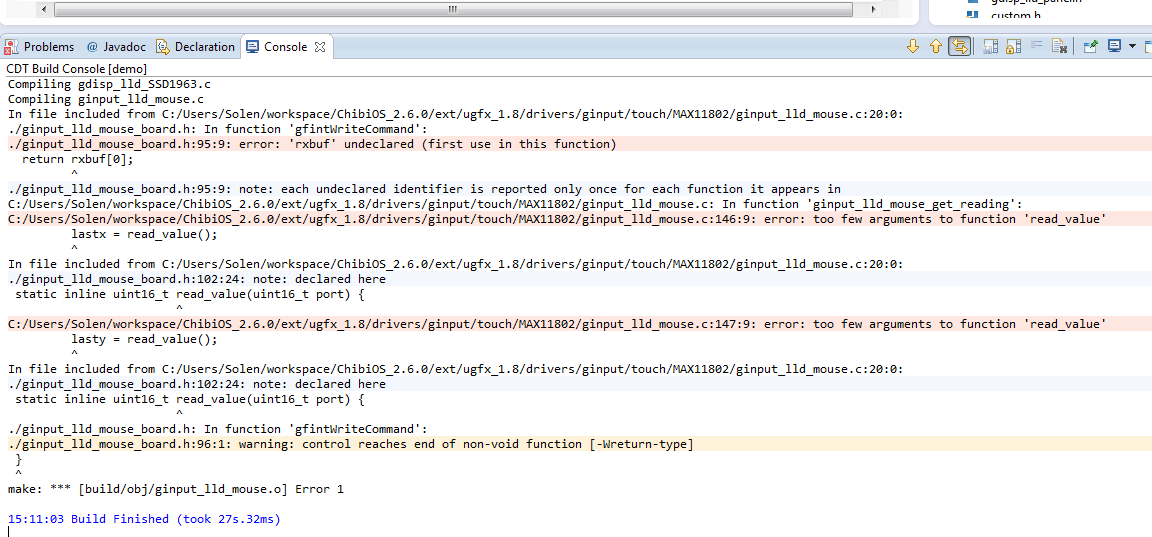
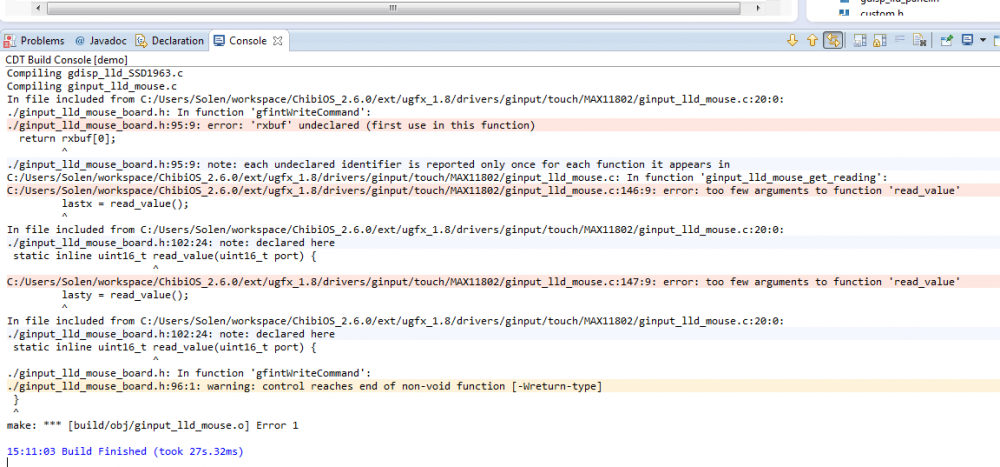
Hi guys, Thanks so much for helping. I've used the files that steved posted but there has been some problems as you can see in the picture where the "ginput_lld_mouse_board.h" file is the file in boards\addons\ginput\touch\MAX11802 from steved's post. Also it says too few arguments to function 'read value'. So the problems seen are mostly based on that file. What can be done to solve this problem? Also if you think that there is something else I can send you my ChibiOS/uGFX file and the project itself. Thanks!!
-
Hi all, I'm new to ARM controllers and touch screens but I'm trying to learn. I wanted to implement the DSO project of naftilos76 to have a better understanding for the future. Like him, I am using the STM32F407 discovery board but I'm using the touch screen INT070ATFT which is 7 inch and has SSD1963 and MAX11802. In the project file which I downloaded from, http://naftilos76.net/dl/tutorial.pdf I've editted the gdisp_lld_panel.h file so that it is compatible with a 7 inch screen but I couldn't know what to change on the ginput_lld_mouse_board.h and ginput_lld_mouse_config.h files because the codes are written for ADS7843 on an Olimex STM32E407 which was available at the drivers section of the ugfx. What do I need to do for it to work on my screen? Also I didn't touched the main.c code, will that change as well? As I said, I'm currently learning and was hoping to make this project work and build on it, so I appreciate any help. Thanks a lot.