

zaher
-
Posts
15 -
Joined
-
Last visited
Content Type
Forums
Store
Downloads
Blogs
Everything posted by zaher
-
Unfortunately, it is exactly the same (0x14, 0x11 ), for my existing driver. Any other proposals?
-
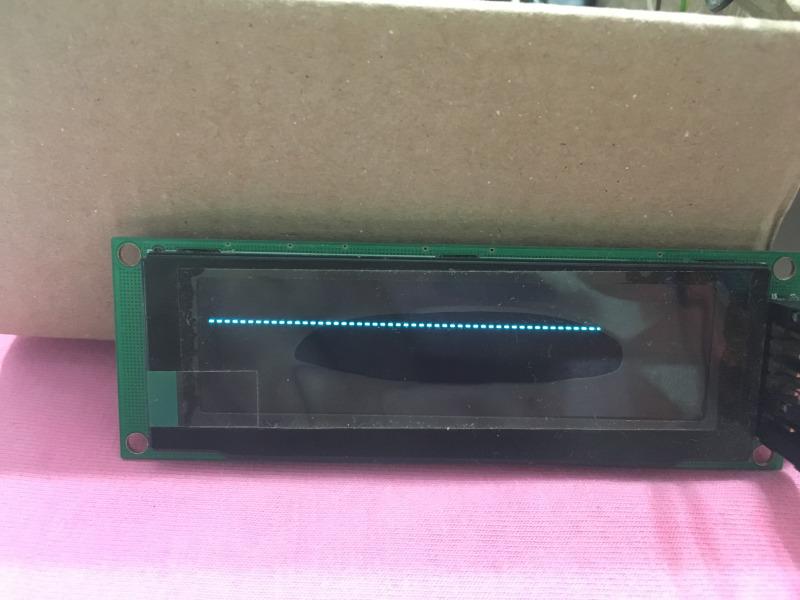
This is the result of drawing a line executing the following: gdispDrawLine(0, 20, 100, 20, White);
-
By the way, I sent a private message to both of you and Joel, but didn't hear back from you yet. It is regarding the uGFX Studio application.
-
Here is my SPI init code: static void MX_SPI2_Init(void) { hspi2.Instance = SPI2; hspi2.Init.Mode = SPI_MODE_MASTER; hspi2.Init.Direction = SPI_DIRECTION_1LINE; hspi2.Init.DataSize = SPI_DATASIZE_8BIT; hspi2.Init.CLKPolarity = SPI_POLARITY_LOW; hspi2.Init.CLKPhase = SPI_PHASE_1EDGE; hspi2.Init.NSS = SPI_NSS_SOFT; hspi2.Init.BaudRatePrescaler = SPI_BAUDRATEPRESCALER_2; hspi2.Init.FirstBit = SPI_FIRSTBIT_MSB; hspi2.Init.TIMode = SPI_TIMODE_DISABLE; hspi2.Init.CRCCalculation = SPI_CRCCALCULATION_DISABLE; hspi2.Init.CRCPolynomial = 7; if (HAL_SPI_Init(&hspi2) != HAL_OK) { Error_Handler(); } } I tried with many different prescalers (4, 16, 32), datasize, clock polarity, nothing worked. And by the way, since the drawing functions from an existing SSD1322 driver work out of the box on the current SPI setup, I doubt the interface has anything to do with it. And this is the init sequence for the SSD1322: LLDSPEC bool_t gdisp_lld_init(GDisplay *g) { // The private area is the display surface. g->priv = gfxAlloc(GDISP_SCREEN_HEIGHT * SSD1322_ROW_WIDTH); // Initialise the board interface init_board(g); post_init_board(g); // Hardware reset HAL_GPIO_WritePin(LCD_RESET_GPIO_Port, LCD_RESET_Pin, SET); HAL_Delay(50); HAL_GPIO_WritePin(LCD_RESET_GPIO_Port, LCD_RESET_Pin, RESET); HAL_Delay(100); HAL_GPIO_WritePin(LCD_RESET_GPIO_Port, LCD_RESET_Pin, SET); HAL_Delay(40); write_cmd(g,CMD_SET_COMMAND_LOCK); write_data(g,0x12); // Unlock OLED driver IC write_cmd(g,CMD_SET_DISPLAY_OFF); write_cmd(g,CMD_SET_CLOCK_DIVIDER); write_data(g,0x91); write_cmd(g,CMD_SET_MULTIPLEX_RATIO); write_data(g,0x3F); //duty = 1/64*,64 COMS are enabled write_cmd(g,CMD_SET_DISPLAY_OFFSET); write_data(g,0x00); write_cmd(g,CMD_SET_DISPLAY_START_LINE); //set start line position write_data(g,0x00); write_cmd(g,CMD_SET_REMAP); write_data(g,0x14); //Horizontal address increment,Disable Column Address Re-map,Enable Nibble Re-map,Scan from COM[N-1] to COM0,Disable COM Split Odd Even write_data(g,0x11); //Enable Dual COM mode write_cmd(g,0xB5); //GPIO write_data(g,0x00); //writeCommand(0x00); write_cmd(g,CMD_SET_FUNCTION_SELECTION); write_data(g,0x01);// selection external VDD write_cmd(g,CMD_DISPLAY_ENHANCEMENT); write_data(g,0xA0);// enables the external VSL write_data(g,0xb5);// 0xfd,Enhanced low GS display quality;default is 0xb5(normal), write_cmd(g,CMD_SET_CONTRAST_CURRENT); write_data(g,0x7f); // 0xff default is 0x7f write_cmd(g,CMD_MASTER_CURRENT_CONTROL); write_data(g,0x0f); //default is 0x0f write_cmd(g,0xB9); //GRAY TABLE,linear Gray Scale write_cmd(g,CMD_SET_PHASE_LENGTH); write_data(g,0xE2); // default is 0x74 write_cmd(g,CMD_DISPLAY_ENHANCEMENT_B); write_data(g,0xA2); // Reserved;default is 0xa2(normal) write_data(g,0x20); write_cmd(g,CMD_SET_PRECHARGE_VOLTAGE); write_data(g,0x1F); // 0.6xVcc write_cmd(g,CMD_SET_SECOND_PRECHARGE_PERIOD); write_data(g,0x08); // default write_cmd(g,CMD_SET_VCOMH_VOLTAGE ); write_data(g,0x07); // 0.86xVcc;default is 0x04 write_cmd(g,CMD_SET_DISPLAY_MODE_NORMAL); write_cmd(g,CMD_EXIT_PARTIAL_DISPLAY); write_cmd(g,CMD_SET_DISPLAY_ON); // Finish Init post_init_board(g); /* Initialise the GDISP structure */ g->g.Width = GDISP_SCREEN_WIDTH; g->g.Height = GDISP_SCREEN_HEIGHT; g->g.Orientation = GDISP_ROTATE_0; g->g.Powermode = powerOn; g->g.Backlight = GDISP_INITIAL_BACKLIGHT; g->g.Contrast = GDISP_INITIAL_CONTRAST; return TRUE; }
-
It is a 3-wire half-duplex SPI
-
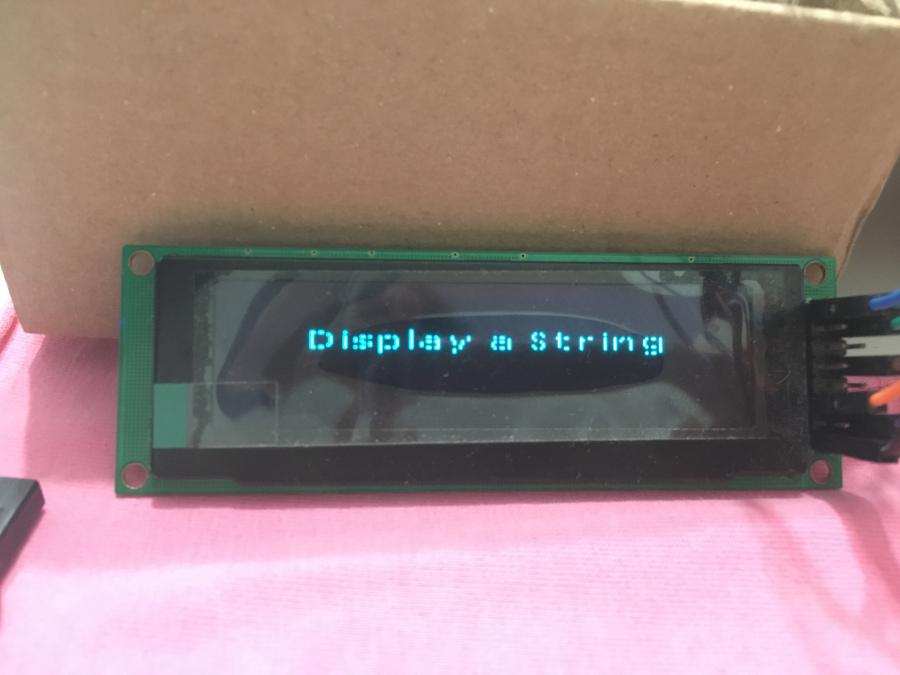
This is another screenshot.
-
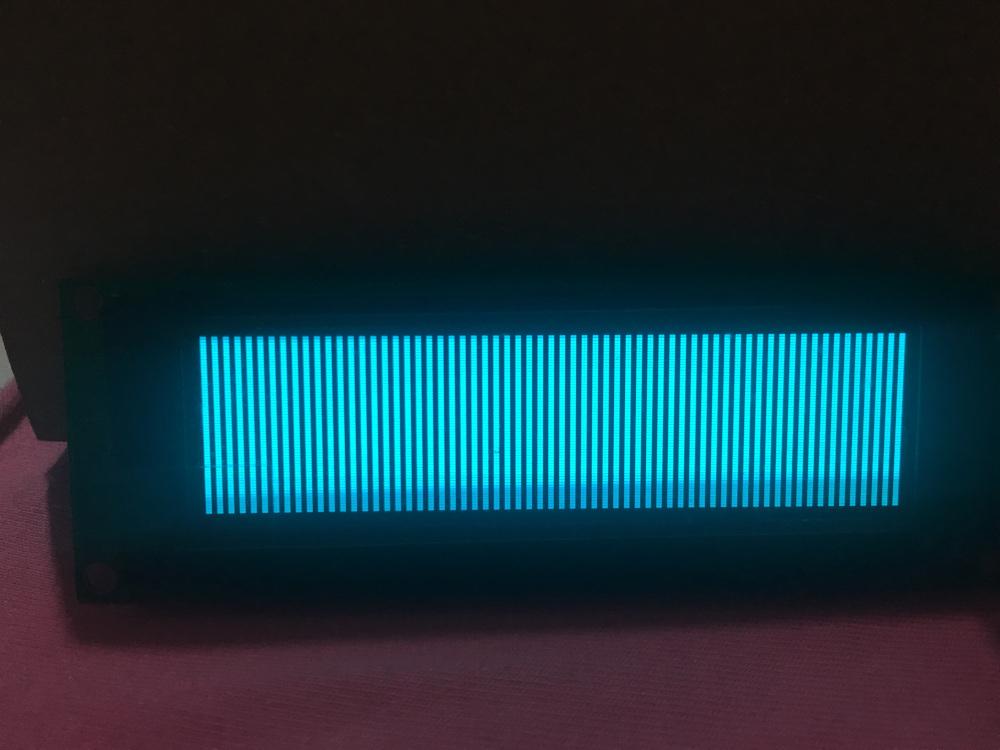
I just realized that everything is being displayed like this on my LCD. This is the result of calling: gdispClear(White); gdispFlush(); These are the defines I have enabled in the _GDISP_LLD_CONFIG_H file: #define GDISP_HARDWARE_FLUSH TRUE // This controller requires flushing #define GDISP_HARDWARE_DRAWPIXEL TRUE #define GDISP_HARDWARE_PIXELREAD TRUE #define GDISP_HARDWARE_CONTROL TRUE #define GDISP_LLD_PIXELFORMAT GDISP_PIXELFORMAT_GRAY16 And here is what I have enabled in gfxconf.h: #define GFX_USE_OS_FREERTOS TRUE #define GFX_OS_NO_INIT TRUE /////////////////////////////////////////////////////////////////////////// // GDISP // /////////////////////////////////////////////////////////////////////////// #define GFX_USE_GDISP TRUE #define GDISP_NEED_AUTOFLUSH FALSE //#define GDISP_NEED_TIMERFLUSH FALSE #define GDISP_NEED_VALIDATION TRUE #define GDISP_NEED_CLIP TRUE #define GDISP_NEED_CIRCLE TRUE #define GDISP_NEED_DUALCIRCLE TRUE #define GDISP_NEED_ELLIPSE TRUE #define GDISP_NEED_ARC TRUE #define GDISP_NEED_ARCSECTORS TRUE #define GDISP_NEED_CONVEX_POLYGON TRUE #define GDISP_NEED_SCROLL TRUE #define GDISP_NEED_PIXELREAD TRUE #define GDISP_NEED_CONTROL TRUE #define GDISP_NEED_TEXT TRUE #define GDISP_NEED_ANTIALIAS TRUE #define GDISP_NEED_UTF8 TRUE #define GDISP_INCLUDE_FONT_UI1 TRUE #define GDISP_INCLUDE_FONT_UI2 TRUE // The smallest preferred font. #define GDISP_INCLUDE_FONT_UI1 TRUE #define GDISP_INCLUDE_FONT_UI2 TRUE // The smallest preferred font. #define GDISP_NEED_STARTUP_LOGO TRUE #define GDISP_TOTAL_DISPLAYS 1 Any ideas?
-
By the way, where I can get more info about each of those defines used in the "gfxconf.h" file?
-
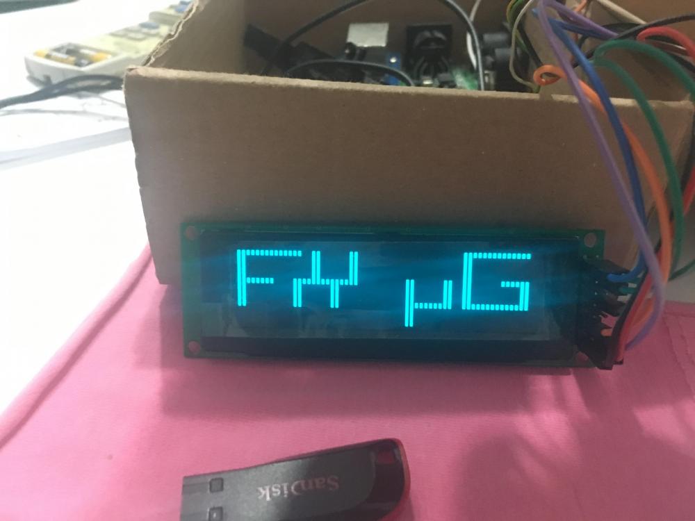
Oh yeah, I was thinking why uG on the right and Fx on the left! Where I need to look at to solve this issue?
-
Thank you guys for the prompt follow up. I guess I'm all set now. I did not touch those functions, and now the display shows the following when initialized: I believe the aforementioned functions are more relevant when a parallel bus is used (FSMC). Since I'm using the SPI and everything was done earlier, I guess I'm good to go. By the way, how to remove this splash screen or it is necessary everytime the system starts up? Thank you again!
-
Hello everyone! I'm almost done adding uGFX to an existing project and now all I need to do to get up and running is to finish the driver glue functions for my LCD. Fortunately, when I came here first time few years ago, the SSD1322 was not supported. Now that has changed and the driver is part of the official repository. Well, I did not try it yet, but out of curiosity and just to make sure everything works out from first time, what is the purpose of the following functions: acquire_bus(GDisplay* g), release_bus(GDisplay* g), post_init_board(GDisplay* g) And why most of these functions, including the write data/command ones, take a pointer of GDisplay type as a parameter? What it does exactly? Thank you! Zaher
-
Hi, I have just managed to integrate the library and compile successfully in Keil uVision 5. My OLED LCD is connected through the 4-wire SPI bus, and I can initialize the LCD and send it commands and data without any problem. I referred to the online documentation, driver templates, and have already got familiar with the structure of the library. However, when it comes to the driver of my LCD itself, I just don't understand where to start and what to look at first. I know that the SSD1322 is not supported by uGFX yet, but it seems someone else had successfully written a driver based on the example/template provided for the SSD1306. For me, I don't mind taking the same approach in writing the driver for my SSD1322 OLED, but I would appreciate any input, guidance, you name it, so I can get where I want faster. in the drivers/gdisp/SSD1306 folder, there are 5 files. Aside from the header file that provides prototypes for functions and variables used by the driver, SSD1306.h, what the other files do and how to customize/add them to the project? Is there any limit to the LCD size/resolution when using the SSD1322 controller with uGFX? Mine is 256x64. By the way, I'm running the bare metal version of the library and I have already enabled the corresponding defines in the gfxconf.h file. Thanks in advance! Zaher
-
Oh, sorry, before I forgot to mention. I was wondering if uGFX incorporates a widget for table views. For example, if I want to display CSV file data in cells (columns and rows). Thank you again! Zaher
-
Hello Tectu, Thank you very much for the prompt reply, and please excuse me for not getting back sooner as I have been away for a little bit. Your support is awesome, and I really appreciate such an initiative! Well, with the information provided, I will try to follow each and every step you come across in your reply, including the recommended guide/article. Anyways, could you please tell me where I can find the RAW32 Port? I could not find it in the uGFX main archive. Again, if someone could provide a working example for Eclipse-Based IDE, AC6 in particular, I would be grateful for your help! Thank you again! Zaher
-
Hello There! First of all, I would like to thank you all for this great effort in making this awesome GUI available for public! Well, I'm trying to get familiar with ChibiOS/RT and uGFX in parallel, however, I would like to try uGFX on my STM32F429-Discovery Board to display few simple primitives (arcs, circles, lines, text) before going any further with the advanced features, OS-based implementation, and other modules. Basically, I would like to know what are the basic requirements needed to get the GDISP Module to work alone (without any other modules, and without an OS), structure of src and inc files required for a simple build using AC6 (System Workbench for STM32) and gnu-arm-none-eabi compiler. I did not try to import the example using make, as I don't like this approach. I'd rather feel more comfortable when adding srcs and incs manually to my project! Thank you for your help!
