

ep.hobbyiest
-
Posts
31 -
Joined
-
Last visited
Content Type
Forums
Store
Downloads
Blogs
Posts posted by ep.hobbyiest
-
-
I am using ugfx library version V2.7
I tried OPT_CPU = stm32m3, but no effect. Screen is blank with no backlight.
-
Yes, I am using Makefile approach.
I am using eclipse configure for chibi os(Chibistudio).
My updated code is here https://github.com/epsgui/ssd1289
-
21 hours ago, cpu20 said:
As for your code there is an example in boards/addons/gdisp for your driver which has a slightly different configuration than yours. Maybe try those settings out also and see if it gives any difference?
Yeah, I changed the file little bit.
Change 1:
Here i was getting error for structure pointer of GDisplay type. so, i commented that part. Following is the error.In file included from main.c:20:0: board_SSD1289.h: In function 'init_board': board_SSD1289.h:60:4: error: dereferencing pointer to incomplete type g->board = 0; ^
Change 2:
And next different is in function of setpin_reset where i am setting or clearing RESET pin. Following is my change.static GFXINLINE void setpin_reset(GDisplay *g, bool_t state) { (void) g; if(state) palClearPad(GPIOB, 11); else palSetPad(GPIOB, 11);//todo: define pins tft }Change 3:
I am using TM3 ch2 for Backlight instead of TM3 CH3. TM3 CH3 is used in boards/addons/gdisp/board_SSD1289_stm32f4discovery.h file.
I can try reverting change 2 and 3 but i try to resolve the error in Change 1 but i couldn't.
-
Hi,
Any suggestion, I have updated my code and following my observation.
Controller is not stuck anywhere it is blinking led continously.
RS,RD,WR , D0-D15 volatge- Still no data
RESET - 3.3
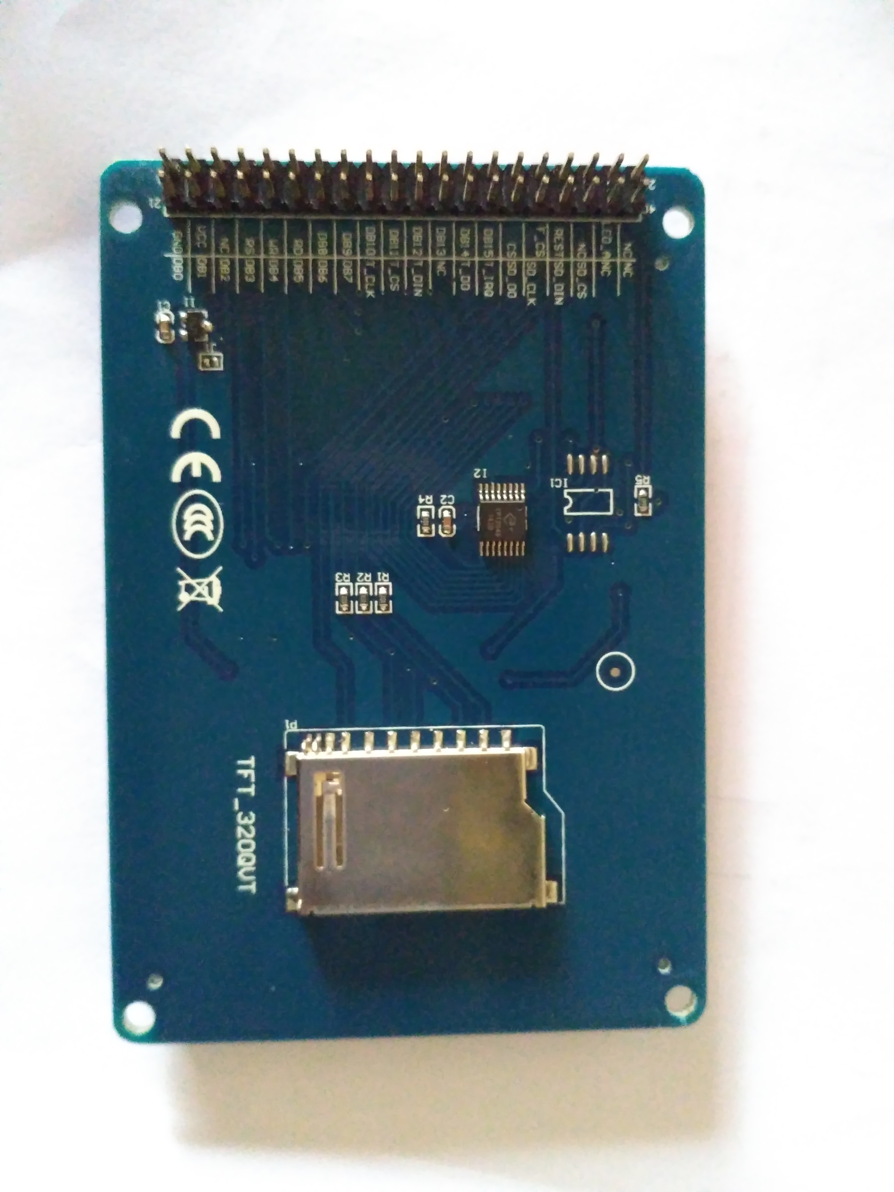
CS - 3.3 For my lcd there are two CS pins and names are as CS and F_CS. Here i am confused. I tried on both pins but none of them is working.
Here is my lcd pic.
http://obrazki.elektroda.pl/6457813100_1494433917.jpg
Any suggest can help. No clue to proceed further.
-
Sorry, code was not in sync. I have synced code with github and attached here as well.
https://github.com/epsgui/ssd1289
-
Yes. I have connected GPIOD and GPIOE port to LCD as These ports are only multiplexed with FSMC.
I am using STM32F103xEx processor.
And before modifying code there was GPIOA port only.
please correct me if i understood wrongly.
-
Hi,
I was trying without DMA and with following interface connection.* PD0 - Alternate PP 50M (FSMC_DB2) * PD1 - Alternate PP 50M (FSMC_DB3) * PD4 - Alternate PP 50M (TFT_RD) * PD5 - Alternate PP 50M (TFT_WR) * PD7 - Alternate PP 50M (TFT_CS) * PD8 - Alternate PP 50M (FSMC_DB13) * PD9 - Alternate PP 50M (FSMC_DB14) * PD10 - Alternate PP 50M (FSMC_DB15) * PD11 - Alternate PP 50M (TFT_RS - Data/Command) * PD12 - Alternate PP 50M (PWM2 CON3.3 TIM4_CH1) * PD13 - PP output 50M (LED3) * PD14 - Alternate PP 50M (FSMC_DB0) * PD15 - Alternate PP 50M (FSMC_DB1) * PE7 - Alternate PP 50M (FSMC_DB4) * PE8 - Alternate PP 50M (FSMC_DB5) * PE9 - Alternate PP 50M (FSMC_DB6) * PE10 - Alternate PP 50M (FSMC_DB7) * PE11 - Alternate PP 50M (FSMC_DB8) * PE12 - Alternate PP 50M (FSMC_DB9) * PE13 - Alternate PP 50M (FSMC_DB10) * PE14 - Alternate PP 50M (FSMC_DB11) * PE15 - Alternate PP 50M (FSMC_DB12) * PB11 - RESET
I flashed the code but nothing is working. I checked the connection but it seems to be fine. I am blinking led at 500ms periodicity and it is blinking. Means there is no stuck.
Here is my observation,
No Backlight,
RESET,CS,RS,RW,RD pins were HIGH(+3.3V). But there was no voltage on DATA pins.
What could be the reason.
-
8 hours ago, phofman said:
ep.hobbyiest: The vendor has confirmed to me several times the display is actually using ILI9481. I asked him to fix the description, to no avail... He sent some code examples, presumably code for displaying the photos as shown on the product page. This time the driver file was called ILI9325.c, in directory called ILI9328 :-) But the init sequence in the file seemed to fit ILI9481 datasheet so he kind of convinced me it was ILI9481. Plus there is another seller with https://www.aliexpress.com/item/4-6-inch-HD-TFT-LCD-Touch-Screen-with-Adapter-Board-ILI9481-Drive-IC-480-272/32669045798.html which looks identical to me, for the same price.
I guess he don't know, what he is selling.
That's really great way to recognize correct way.
Can you please share some details here.
-
Because last time you mentioned TFT ILI9486
But here you are mentioning ILI9481.
Can you please tell us which tft LCD you used? So, we can order the same lcd.
-
Hi,
I have deleted the repo and organization. I have updated code in following branch.
https://github.com/epsgui/ssd1289
-
Great Work.
Can you please tell us which tft LCD you used? So, we can order the same lcd.
-
Hi,
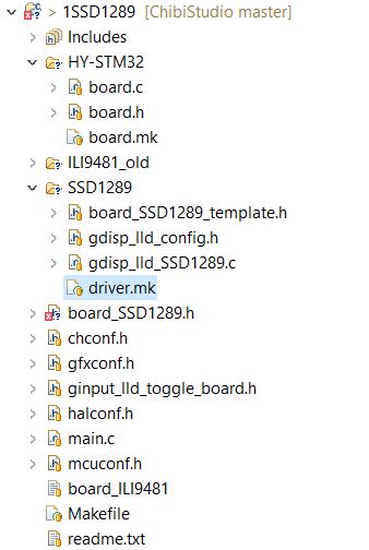
I have some doubt from SSD1289 board file. I have TFT_320QVT lcd which has ssd1289 controller in it.
I copied SSD1289 driver folder in project.But i am little confused about pin configuration and interface.
I have enabled DMA here. So, will it cause double writing on PORT or something.
We are writing data to memory location. So, FSMC will take case of that or DMA will take care.
static GFXINLINE void init_board(GDisplay *g) { /* * As we are not using multiple displays we set g->board to NULL as we don't * use it. */ // g->board = 0; // // switch(g->controllerdisplay) { // /* // * Set up for Display 0 // */ // case 0: /* FSMC setup for F1 */ rccEnableAHB(RCC_AHBENR_FSMCEN, 0); /* Group pins for FSMC setup as alternate function */ IOBus busD = { GPIOA, (1 << 0) | (1 << 1) | (1 << 4) | (1 << 5) | \ (1 << 7) | (1 << 8) | (1 << 9) | (1 << 10) | (1 << 11) | \ (1 << 14) | (1 << 15), 0 }; IOBus busE = { GPIOE, (1 << 7) | (1 << 8) | (1 << 9) | (1 << 10) | \ (1 << 11) | (1 << 12) | (1 << 13) | (1 << 14) | \ (1 << 15), 0 }; /* FSMC sa alternate function */ palSetBusMode(&busD, PAL_MODE_STM32_ALTERNATE_PUSHPULL); palSetBusMode(&busE, PAL_MODE_STM32_ALTERNATE_PUSHPULL); /* * NOTE: stm32F10x.h is FAULTY on FSMC * NOTE: Used hardcore bit shifting below * NOTE: All timings for 72MHz HCLK - should be revised for lower HCLK */ /* FSMC timing - Read: DATAST = 0x20; all the rest = 0. * 100ns cycle time for SSD1289 as per DataSheet */ FSMC_Bank1->BTCR[FSMC_BANK+1] = (0x20 << 8); /* FSMC timing - Write: DATAST = 0x01, ADDSET = 0x01 all the rest = 0. * 1000ns cycle time for SSD1289 as per DataSheet */ FSMC_Bank1E->BWTR[FSMC_BANK] = (0x1 << 8) | (0x01 << 0); /* Bank1 NOR/SRAM control register configuration * Note: different read and write cycle timing */ FSMC_Bank1->BTCR[FSMC_BANK] = FSMC_BCR1_MWID_0 | FSMC_BCR1_WREN | \ FSMC_BCR1_MBKEN | FSMC_BCR1_EXTMOD; /* DMA Setup. */ #if defined(GDISP_USE_DMA) && defined(GDISP_DMA_STREAM) if (dmaStreamAllocate(GDISP_DMA_STREAM, 0, 0, 0)) gfxExit(); dmaStreamSetMemory0(GDISP_DMA_STREAM, &GDISP_RAM); dmaStreamSetMode(GDISP_DMA_STREAM, STM32_DMA_CR_PL(0) | \ STM32_DMA_CR_PSIZE_HWORD | STM32_DMA_CR_MSIZE_HWORD | \ STM32_DMA_CR_DIR_M2M); #endif /* Display backlight control */ /* TIM3 ch2 (PB5) connected to LCD BL_CNT */ pwmStart(&PWMD3, &pwmcfg); palSetPadMode(GPIOB, 5, PAL_MODE_STM32_ALTERNATE_PUSHPULL); pwmEnableChannel(&PWMD3, 1, 100); // break; // } }Here is picture of lcd i have.
http://obrazki.elektroda.pl/6457813100_1494433917.jpg
And i have updated code on github . https://github.com/ugfx/ssd1289
Thanks.
-
On 5/8/2017 at 01:29, phofman said:
I am working on integrating the inexpensive 4.63" LCD https://www.aliexpress.com/item/4-63-inch-16-9-272-480-TFT-screen-with-Resistance-touch-and-PCB-panel-LCM/32802272563.html with chibios on STM32F103, will report when finished.
That's great. Let me know where i can help. And i will do it parallely as well.
-
SSD1963 this gonna take some time for shipping. Now, I can try with SSD1289.
-
Hi,
Thanks for the great solution.
Cost: I am mainly looking for availability and in that cost. I am not looking for cheaper solution nor more costly.
4.3 inch will work for me.
I am using STM32 in my project and i never work on linux board before. So, i am preferring STM32 controller.
I don't have dedicated board to start work on GUI. I have other board, But for beginner it would be better to have working things to get some confidence.
-
1 hour ago, Alvin said:
I don't think there's that many good options for a 5inch display.
Which option are you talking about?
-
yes, right i dont want to use RGB interface board.
But how about other display
http://www.buydisplay.com/default/5-tft-lcd-display-module-wvga-800x480-high-resolution-for-mp4-gps
http://www.buydisplay.com/default/lcd-5-inch-display-480x272-tft-module-touch-screen-for-mp4-gps
Are they good?
Does anyone interface this/similar display's ?
Do you know any dev board or other board? So, i can test the display and later i can go for my own pcb.
I have discovery stm32f411 board.
-
ohh... yes.
I don't want to face this problem.
We can go with parallel method(8/16-bit).
Then which kind of inexpensive lcd's are used here mostly. I tried last time 3.2 inch lcd which got blown out(without making it work).
following type lcd's i found (Without criteria)
http://www.winstar.com.tw/products/tft-lcd/module/5-tft-lcd.html
http://www.buydisplay.com/default/tft-5-inch-lcd-display-module-controller-board-serial-i2c-ra8875
http://www.buydisplay.com/default/5-tft-lcd-display-module-wvga-800x480-high-resolution-for-mp4-gps
http://www.buydisplay.com/default/lcd-5-inch-display-480x272-tft-module-touch-screen-for-mp4-gps
-
Hi,
I was looking for GUI solution last time, But due to other work i suspended this one.
I have Discovery board STM32F411.
I want to display some temperature and some data. So, I want to use 5 inch with resistive touch.
Not fast refresh required, but screen loading should not be display.
Few screens might be there.
So, I have following doubt.
1. Is SPI interface will be suitable for my application?
2. Which TFT lcd Controller is compatible with STM32 and ugfx i should use?
3. Do i require extra memory if screen's are more than 6? Mostly i will be using Text only.
-
I think 3.2 inch or bit larger is sufficient for me. I ll be using stm32f controller.
-
Thanks for suggestion.
i thought of using 16-bit only, but to save some pins i was thinking. but thanks for changing my mind again.
I am looking for resistive touch and bit cheaper option. I ll be using it to show temperature of oven using widgets and to adjust it using touch screen.
-
Hi,
i am looking for 8-bit parallel touch screen lcd and 4-5 inch big. I ll be using stm32, chibi os. So, please suggest me some lcd which can give good effect on ugfx stack.
-
Thanks Joel.
Problem is solved now. And sorry for late update as i was out of city for some days.
Is that configuration okay for ili9341 lcd for 8-bit mode? -
Hi,
I got configured one project. But facing some problem in initial phase. Following are the my attached configured files.
And i got some error which are saying multiple definition but i searched my project i got only one definition.
I am configuring ili9341 tft in 8-bit.
controller is stm32f103rb.
OS is Chibios.
got error while configuring for windows simulation
in Support
Posted
Hi,
i was trying to configure uGFX for windows machine and i was following following page.
https://wiki.ugfx.io/index.php/Your_First_Compile_-_Windows
I installed cygwin and it;s package properly. and set the folder structure too. But i got following error while compliling example code for win32.
make: mkdir: Command not found
make: *** [../uGFX/tools/gmake_scripts/compiler_gcc.mk:193: builddirs] Error 127
I am using Windows 10.
and folder structure is under X:/abc/
No space is in directory structure.