

ep.hobbyiest
-
Posts
31 -
Joined
-
Last visited
-
Hi, i was trying to configure uGFX for windows machine and i was following following page. https://wiki.ugfx.io/index.php/Your_First_Compile_-_Windows I installed cygwin and it;s package properly. and set the folder structure too. But i got following error while compliling example code for win32. make: mkdir: Command not found make: *** [../uGFX/tools/gmake_scripts/compiler_gcc.mk:193: builddirs] Error 127 I am using Windows 10. and folder structure is under X:/abc/ No space is in directory structure.
-
I am using ugfx library version V2.7 I tried OPT_CPU = stm32m3, but no effect. Screen is blank with no backlight.
-
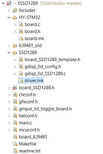
Yes, I am using Makefile approach. I am using eclipse configure for chibi os(Chibistudio). My updated code is here https://github.com/epsgui/ssd1289
-
Yeah, I changed the file little bit. Change 1: Here i was getting error for structure pointer of GDisplay type. so, i commented that part. Following is the error. In file included from main.c:20:0: board_SSD1289.h: In function 'init_board': board_SSD1289.h:60:4: error: dereferencing pointer to incomplete type g->board = 0; ^ Change 2: And next different is in function of setpin_reset where i am setting or clearing RESET pin. Following is my change. static GFXINLINE void setpin_reset(GDisplay *g, bool_t state) { (void) g; if(state) palClearPad(GPIOB, 11); else palSetPad(GPIOB, 11);//todo: define pins tft } Change 3: I am using TM3 ch2 for Backlight instead of TM3 CH3. TM3 CH3 is used in boards/addons/gdisp/board_SSD1289_stm32f4discovery.h file. I can try reverting change 2 and 3 but i try to resolve the error in Change 1 but i couldn't.
-
Hi, Any suggestion, I have updated my code and following my observation. Controller is not stuck anywhere it is blinking led continously. RS,RD,WR , D0-D15 volatge- Still no data RESET - 3.3 CS - 3.3 For my lcd there are two CS pins and names are as CS and F_CS. Here i am confused. I tried on both pins but none of them is working. Here is my lcd pic. http://obrazki.elektroda.pl/6457813100_1494433917.jpg Any suggest can help. No clue to proceed further.
-
Sorry, code was not in sync. I have synced code with github and attached here as well. https://github.com/epsgui/ssd1289 ssd1289.7z
-
Yes. I have connected GPIOD and GPIOE port to LCD as These ports are only multiplexed with FSMC. I am using STM32F103xEx processor. And before modifying code there was GPIOA port only. please correct me if i understood wrongly.
-
Hi, I was trying without DMA and with following interface connection. * PD0 - Alternate PP 50M (FSMC_DB2) * PD1 - Alternate PP 50M (FSMC_DB3) * PD4 - Alternate PP 50M (TFT_RD) * PD5 - Alternate PP 50M (TFT_WR) * PD7 - Alternate PP 50M (TFT_CS) * PD8 - Alternate PP 50M (FSMC_DB13) * PD9 - Alternate PP 50M (FSMC_DB14) * PD10 - Alternate PP 50M (FSMC_DB15) * PD11 - Alternate PP 50M (TFT_RS - Data/Command) * PD12 - Alternate PP 50M (PWM2 CON3.3 TIM4_CH1) * PD13 - PP output 50M (LED3) * PD14 - Alternate PP 50M (FSMC_DB0) * PD15 - Alternate PP 50M (FSMC_DB1) * PE7 - Alternate PP 50M (FSMC_DB4) * PE8 - Alternate PP 50M (FSMC_DB5) * PE9 - Alternate PP 50M (FSMC_DB6) * PE10 - Alternate PP 50M (FSMC_DB7) * PE11 - Alternate PP 50M (FSMC_DB8) * PE12 - Alternate PP 50M (FSMC_DB9) * PE13 - Alternate PP 50M (FSMC_DB10) * PE14 - Alternate PP 50M (FSMC_DB11) * PE15 - Alternate PP 50M (FSMC_DB12) * PB11 - RESET I flashed the code but nothing is working. I checked the connection but it seems to be fine. I am blinking led at 500ms periodicity and it is blinking. Means there is no stuck. Here is my observation, No Backlight, RESET,CS,RS,RW,RD pins were HIGH(+3.3V). But there was no voltage on DATA pins. What could be the reason.
-
I guess he don't know, what he is selling. That's really great way to recognize correct way. Can you please share some details here.
-
Because last time you mentioned TFT ILI9486 https://www.aliexpress.com/item/4-63-inch-16-9-272-480-TFT-screen-with-Resistance-touch-and-PCB-panel-LCM/32802272563.html But here you are mentioning ILI9481. Can you please tell us which tft LCD you used? So, we can order the same lcd.
-
Hi, I have deleted the repo and organization. I have updated code in following branch. https://github.com/epsgui/ssd1289
-
Great Work. Can you please tell us which tft LCD you used? So, we can order the same lcd.
-
Hi, I have some doubt from SSD1289 board file. I have TFT_320QVT lcd which has ssd1289 controller in it. I copied SSD1289 driver folder in project. But i am little confused about pin configuration and interface. I have enabled DMA here. So, will it cause double writing on PORT or something. We are writing data to memory location. So, FSMC will take case of that or DMA will take care. static GFXINLINE void init_board(GDisplay *g) { /* * As we are not using multiple displays we set g->board to NULL as we don't * use it. */ // g->board = 0; // // switch(g->controllerdisplay) { // /* // * Set up for Display 0 // */ // case 0: /* FSMC setup for F1 */ rccEnableAHB(RCC_AHBENR_FSMCEN, 0); /* Group pins for FSMC setup as alternate function */ IOBus busD = { GPIOA, (1 << 0) | (1 << 1) | (1 << 4) | (1 << 5) | \ (1 << 7) | (1 << 8) | (1 << 9) | (1 << 10) | (1 << 11) | \ (1 << 14) | (1 << 15), 0 }; IOBus busE = { GPIOE, (1 << 7) | (1 << 8) | (1 << 9) | (1 << 10) | \ (1 << 11) | (1 << 12) | (1 << 13) | (1 << 14) | \ (1 << 15), 0 }; /* FSMC sa alternate function */ palSetBusMode(&busD, PAL_MODE_STM32_ALTERNATE_PUSHPULL); palSetBusMode(&busE, PAL_MODE_STM32_ALTERNATE_PUSHPULL); /* * NOTE: stm32F10x.h is FAULTY on FSMC * NOTE: Used hardcore bit shifting below * NOTE: All timings for 72MHz HCLK - should be revised for lower HCLK */ /* FSMC timing - Read: DATAST = 0x20; all the rest = 0. * 100ns cycle time for SSD1289 as per DataSheet */ FSMC_Bank1->BTCR[FSMC_BANK+1] = (0x20 << 8); /* FSMC timing - Write: DATAST = 0x01, ADDSET = 0x01 all the rest = 0. * 1000ns cycle time for SSD1289 as per DataSheet */ FSMC_Bank1E->BWTR[FSMC_BANK] = (0x1 << 8) | (0x01 << 0); /* Bank1 NOR/SRAM control register configuration * Note: different read and write cycle timing */ FSMC_Bank1->BTCR[FSMC_BANK] = FSMC_BCR1_MWID_0 | FSMC_BCR1_WREN | \ FSMC_BCR1_MBKEN | FSMC_BCR1_EXTMOD; /* DMA Setup. */ #if defined(GDISP_USE_DMA) && defined(GDISP_DMA_STREAM) if (dmaStreamAllocate(GDISP_DMA_STREAM, 0, 0, 0)) gfxExit(); dmaStreamSetMemory0(GDISP_DMA_STREAM, &GDISP_RAM); dmaStreamSetMode(GDISP_DMA_STREAM, STM32_DMA_CR_PL(0) | \ STM32_DMA_CR_PSIZE_HWORD | STM32_DMA_CR_MSIZE_HWORD | \ STM32_DMA_CR_DIR_M2M); #endif /* Display backlight control */ /* TIM3 ch2 (PB5) connected to LCD BL_CNT */ pwmStart(&PWMD3, &pwmcfg); palSetPadMode(GPIOB, 5, PAL_MODE_STM32_ALTERNATE_PUSHPULL); pwmEnableChannel(&PWMD3, 1, 100); // break; // } } Here is picture of lcd i have. http://obrazki.elektroda.pl/6457813100_1494433917.jpg And i have updated code on github . https://github.com/ugfx/ssd1289 Thanks.
-
looking for GUI solution with 5 inch display
ep.hobbyiest replied to ep.hobbyiest's topic in Support
That's great. Let me know where i can help. And i will do it parallely as well. -
looking for GUI solution with 5 inch display
ep.hobbyiest replied to ep.hobbyiest's topic in Support
SSD1963 this gonna take some time for shipping. Now, I can try with SSD1289.