tombalabomba
-
Posts
18 -
Joined
-
Last visited
-
uGFX + FreeRtos + STM32L1 + stucked vTaskStartScheduler()
tombalabomba replied to tombalabomba's topic in Support
Hi, I guess I can close this issue. I wrongly suspected the uGFX lib to be part of the problem. The root cause was that I modified the code of by RAW_32 implementation for using FreeRtos. Since I used CubeMx for HAL generation, I just had to remove HAL_NVIC_SetPriorityGrouping(NVIC_PRIORITYGROUP_0) in the HAL_MspInit() routine of the corresponding MCU support package file. By the way. I''m not able to use link, code and file upload tools of this homepage anymore. Apparently, something has changed since it perfectly worked a couple of months ago. -
Hi folks, I face problems to get ugfx and freertos running. Essentially, I followed the demo CPU20 has made for a STM32F7 bord. The code of my main.c is at the bottom of this post. I'm sorry for the unprofessional appearance. Unfortunatly, wehter code insertion nor file upload works with the tested browsers (chrome, firefox, edge). I first checked if the FreeRtos works before I imported the ugfx lib. Since everthing seemed to be OK I tired ugfx in RAW_32 mode by setting #define GFX_USE_OS_RAW32 GFXON #define GFX_USE_GDISP GFXON #define GDISP_NEED_TEXT GFXON #define GDISP_INCLUDE_FONT_DEJAVUSANS16 GFXON in gfxconf.h. Conclusio: Everything is ok. Then I changed in gfxconf.h: #define GFX_USE_OS_RAW32 GFXOFF #define GFX_USE_OS_FREERTOS GFXON #define GFX_OS_HEAP_SIZE 4096 #define GFX_OS_NO_INIT GFXON Now the problem is that the system gets stuck as soon vTaskStartScheduler() is called. I tried to debug it but it never reaches one of the tasks. Any help is kindly apprechiated! /** ****************************************************************************** * @file main.c * @author Ac6 * @version V1.0 * @date 01-December-2013 * @brief Default main function. ****************************************************************************** */ #include <board_ILI9225.h> #include "stm32l1xx_hal.h" #include "FreeRTOS.h" #include "task.h" #include "gfx.h" void SystemClock_Config(void); static void GPIO_Init(void); static void I2C_Init(void); static void SPI_Init(void); void Error_Handler(void); TaskHandle_t uGFXInitTask; I2C_HandleTypeDef hi2c1; SPI_HandleTypeDef hspi2; //----------------------------------------------------------------------------- void uGFXUpdate(void* pvParameters) { (void)pvParameters; font_t font = gdispOpenFont("DejaVuSans16"); while (1) { gdispFillString(10, 10, "uGFX FreeRTOS", font, White, Black); HAL_GPIO_TogglePin(LD2_GPIO_Port, LD2_Pin); vTaskDelay(500/portTICK_PERIOD_MS); } } //----------------------------------------------------------------------------- void uGFXInit(void* pvParameters) { (void)pvParameters; while (1) { gfxInit(); xTaskCreate(uGFXUpdate,"uGFXUpdate", 200, NULL, 0, NULL); vTaskDelete(uGFXInitTask); } } //----------------------------------------------------------------------------- int main(void) { HAL_Init(); SystemClock_Config(); GPIO_Init(); SPI_Init(); I2C_Init(); #if GFX_USE_OS_FREERTOS == GFXON xTaskCreate(uGFXInit, "uGFXInit", 200, NULL, 0, &uGFXInitTask); vTaskStartScheduler(); #elif GFX_USE_OS_RAW32 == GFXON font_t font = gdispOpenFont("DejaVuSans16"); gfxInit(); while(1){ gdispFillString(10, 10, "GFX_RAW_32", font, White, Black); HAL_GPIO_TogglePin(LD2_GPIO_Port, LD2_Pin); gfxSleepMilliseconds(200); } #endif for (;;); } //----------------------------------------------------------------------------- void SystemClock_Config(void) { RCC_OscInitTypeDef RCC_OscInitStruct = {0}; RCC_ClkInitTypeDef RCC_ClkInitStruct = {0}; /**Configure the main internal regulator output voltage */ __HAL_PWR_VOLTAGESCALING_CONFIG(PWR_REGULATOR_VOLTAGE_SCALE1); /**Initializes the CPU, AHB and APB busses clocks */ RCC_OscInitStruct.OscillatorType = RCC_OSCILLATORTYPE_HSI; RCC_OscInitStruct.HSIState = RCC_HSI_ON; RCC_OscInitStruct.HSICalibrationValue = RCC_HSICALIBRATION_DEFAULT; RCC_OscInitStruct.PLL.PLLState = RCC_PLL_ON; RCC_OscInitStruct.PLL.PLLSource = RCC_PLLSOURCE_HSI; RCC_OscInitStruct.PLL.PLLMUL = RCC_PLL_MUL6; RCC_OscInitStruct.PLL.PLLDIV = RCC_PLL_DIV3; if (HAL_RCC_OscConfig(&RCC_OscInitStruct) != HAL_OK) { Error_Handler(); } /**Initializes the CPU, AHB and APB busses clocks */ RCC_ClkInitStruct.ClockType = RCC_CLOCKTYPE_HCLK|RCC_CLOCKTYPE_SYSCLK |RCC_CLOCKTYPE_PCLK1|RCC_CLOCKTYPE_PCLK2; RCC_ClkInitStruct.SYSCLKSource = RCC_SYSCLKSOURCE_PLLCLK; RCC_ClkInitStruct.AHBCLKDivider = RCC_SYSCLK_DIV1; RCC_ClkInitStruct.APB1CLKDivider = RCC_HCLK_DIV1; RCC_ClkInitStruct.APB2CLKDivider = RCC_HCLK_DIV1; if (HAL_RCC_ClockConfig(&RCC_ClkInitStruct, FLASH_LATENCY_1) != HAL_OK) { Error_Handler(); } } //----------------------------------------------------------------------------- static void I2C_Init(void) { /* USER CODE BEGIN I2C1_Init 0 */ /* USER CODE END I2C1_Init 0 */ /* USER CODE BEGIN I2C1_Init 1 */ /* USER CODE END I2C1_Init 1 */ hi2c1.Instance = I2C1; hi2c1.Init.ClockSpeed = 100000; hi2c1.Init.DutyCycle = I2C_DUTYCYCLE_2; hi2c1.Init.OwnAddress1 = 0; hi2c1.Init.AddressingMode = I2C_ADDRESSINGMODE_7BIT; hi2c1.Init.DualAddressMode = I2C_DUALADDRESS_DISABLE; hi2c1.Init.OwnAddress2 = 0; hi2c1.Init.GeneralCallMode = I2C_GENERALCALL_DISABLE; hi2c1.Init.NoStretchMode = I2C_NOSTRETCH_DISABLE; if (HAL_I2C_Init(&hi2c1) != HAL_OK) { Error_Handler(); } /* USER CODE BEGIN I2C1_Init 2 */ /* USER CODE END I2C1_Init 2 */ } //----------------------------------------------------------------------------- static void SPI_Init(void) { /* SPI2 parameter configuration*/ hspi2.Instance = SPI2; hspi2.Init.Mode = SPI_MODE_MASTER; hspi2.Init.Direction = SPI_DIRECTION_2LINES; hspi2.Init.DataSize = SPI_DATASIZE_8BIT; hspi2.Init.CLKPolarity = SPI_POLARITY_HIGH; hspi2.Init.CLKPhase = SPI_PHASE_2EDGE; hspi2.Init.NSS = SPI_NSS_SOFT; hspi2.Init.BaudRatePrescaler = SPI_BAUDRATEPRESCALER_2; hspi2.Init.FirstBit = SPI_FIRSTBIT_MSB; hspi2.Init.TIMode = SPI_TIMODE_DISABLE; hspi2.Init.CRCCalculation = SPI_CRCCALCULATION_DISABLE; hspi2.Init.CRCPolynomial = 10; if (HAL_SPI_Init(&hspi2) != HAL_OK) { Error_Handler(); } } //----------------------------------------------------------------------------- static void GPIO_Init(void) { GPIO_InitTypeDef GPIO_InitStruct = {0}; /* GPIO Ports Clock Enable */ __HAL_RCC_GPIOC_CLK_ENABLE(); __HAL_RCC_GPIOH_CLK_ENABLE(); __HAL_RCC_GPIOA_CLK_ENABLE(); __HAL_RCC_GPIOB_CLK_ENABLE(); /*Configure GPIO pin Output Level */ HAL_GPIO_WritePin(LD2_GPIO_Port, LD2_Pin, GPIO_PIN_RESET); /*Configure GPIO pin Output Level */ HAL_GPIO_WritePin(GPIOB, LCD_RS_Pin|LCD_RST_Pin|LCD_CS_Pin, GPIO_PIN_RESET); /*Configure GPIO pin : B1_Pin */ GPIO_InitStruct.Pin = B1_Pin; GPIO_InitStruct.Mode = GPIO_MODE_IT_RISING; GPIO_InitStruct.Pull = GPIO_NOPULL; HAL_GPIO_Init(B1_GPIO_Port, &GPIO_InitStruct); /*Configure GPIO pin : LD2_Pin */ GPIO_InitStruct.Pin = LD2_Pin; GPIO_InitStruct.Mode = GPIO_MODE_OUTPUT_PP; GPIO_InitStruct.Pull = GPIO_NOPULL; GPIO_InitStruct.Speed = GPIO_SPEED_FREQ_LOW; HAL_GPIO_Init(LD2_GPIO_Port, &GPIO_InitStruct); /*Configure GPIO pins : LCD_RS_Pin LCD_CS_Pin */ GPIO_InitStruct.Pin = LCD_RS_Pin|LCD_CS_Pin; GPIO_InitStruct.Mode = GPIO_MODE_OUTPUT_PP; GPIO_InitStruct.Pull = GPIO_NOPULL; GPIO_InitStruct.Speed = GPIO_SPEED_FREQ_VERY_HIGH; HAL_GPIO_Init(GPIOB, &GPIO_InitStruct); /*Configure GPIO pin : LCD_RST_Pin */ GPIO_InitStruct.Pin = LCD_RST_Pin; GPIO_InitStruct.Mode = GPIO_MODE_OUTPUT_PP; GPIO_InitStruct.Pull = GPIO_NOPULL; GPIO_InitStruct.Speed = GPIO_SPEED_FREQ_LOW; HAL_GPIO_Init(LCD_RST_GPIO_Port, &GPIO_InitStruct); } //----------------------------------------------------------------------------- void Error_Handler(void) { /* USER CODE BEGIN Error_Handler_Debug */ /* User can add his own implementation to report the HAL error return state */ /* USER CODE END Error_Handler_Debug */ }
-
Meanwhile, I ended up with a working configuration. Basically, I had to fix two problems. The first was indeed the wrong SPI configuration. In contrast to many other ILI driver the ILI9225 drivers requires CPOL = 1: hspi2.Init.CLKPolarity = SPI_POLARITY_HIGH; On the other hand there was also a problem with the chip select signal. Controlling CS in acquire_bus(GDisplay* g) and release_bus(GDisplay* g) didn't do the job and I had to control the chip select signal right before and after data transmission.
-
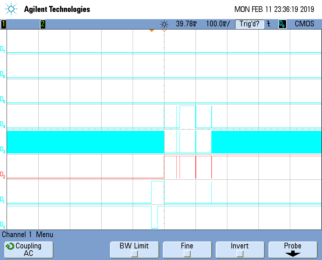
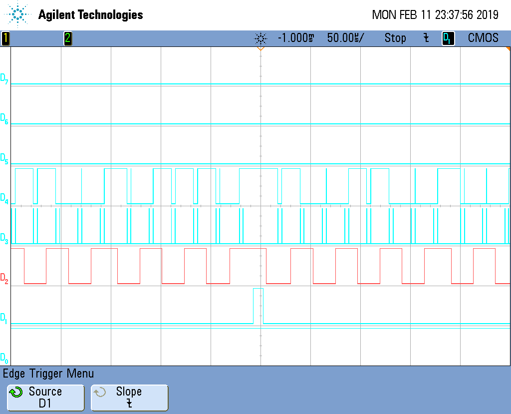
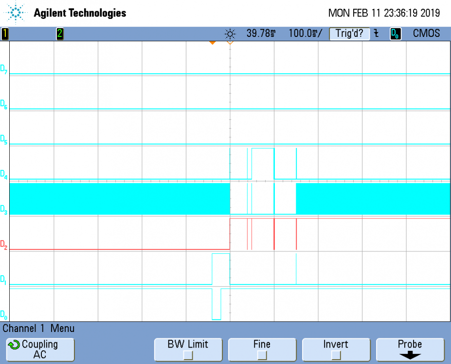
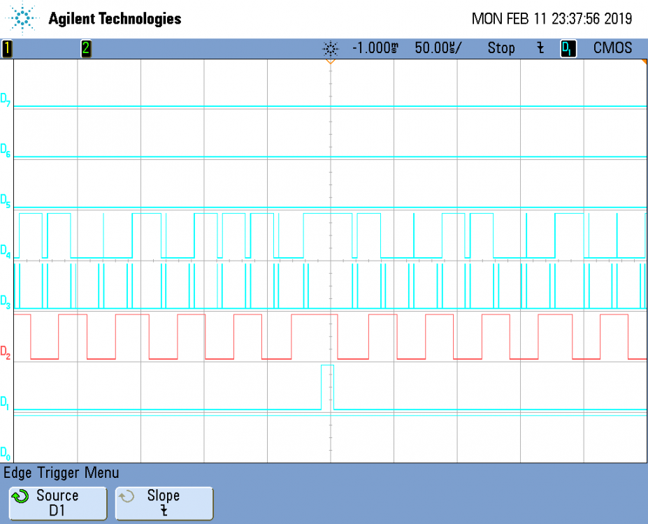
I struggle to get my ILI9225 driven display on a STM32L1 nucleo board running. Essentially. Below you can find my application code and the board file I use. main.c : #include "stm32l1xx.h" #include "stm32l1xx_nucleo.h" #include "gfx.h" #include "stm32l1xx_hal.h" #include "board_ILI9225.h" void SystemClock_Config(void); void Error_Handler(void); int main(void) { coord_t width, height; coord_t i, j; HAL_Init(); SystemClock_Config(); gfxInit(); width = gdispGetWidth(); height = gdispGetHeight(); gdispDrawBox(10, 10, width/2, height/2, Yellow); gdispFillArea(width/2, height/2, width/2-10, height/2-10, Blue); gdispDrawLine(5, 30, width-50, height-40, Red); while (TRUE) { for (i = 5, j = 0; i < width && j < height; i += 7, j += i/20) { gdispDrawPixel(i, j, White); } gfxSleepMilliseconds(500); HAL_GPIO_TogglePin(LD2_PORT, LD2_Pin); } } void SystemClock_Config(void) { RCC_OscInitTypeDef RCC_OscInitStruct = {0}; RCC_ClkInitTypeDef RCC_ClkInitStruct = {0}; /**Configure the main internal regulator output voltage */ __HAL_PWR_VOLTAGESCALING_CONFIG(PWR_REGULATOR_VOLTAGE_SCALE1); /**Initializes the CPU, AHB and APB busses clocks */ RCC_OscInitStruct.OscillatorType = RCC_OSCILLATORTYPE_HSE; RCC_OscInitStruct.HSEState = RCC_HSE_BYPASS; RCC_OscInitStruct.PLL.PLLState = RCC_PLL_ON; RCC_OscInitStruct.PLL.PLLSource = RCC_PLLSOURCE_HSE; RCC_OscInitStruct.PLL.PLLMUL = RCC_PLL_MUL12; RCC_OscInitStruct.PLL.PLLDIV = RCC_PLL_DIV3; if (HAL_RCC_OscConfig(&RCC_OscInitStruct) != HAL_OK) { Error_Handler(); } /**Initializes the CPU, AHB and APB busses clocks */ RCC_ClkInitStruct.ClockType = RCC_CLOCKTYPE_HCLK|RCC_CLOCKTYPE_SYSCLK |RCC_CLOCKTYPE_PCLK1|RCC_CLOCKTYPE_PCLK2; RCC_ClkInitStruct.SYSCLKSource = RCC_SYSCLKSOURCE_PLLCLK; RCC_ClkInitStruct.AHBCLKDivider = RCC_SYSCLK_DIV1; RCC_ClkInitStruct.APB1CLKDivider = RCC_HCLK_DIV1; RCC_ClkInitStruct.APB2CLKDivider = RCC_HCLK_DIV1; if (HAL_RCC_ClockConfig(&RCC_ClkInitStruct, FLASH_LATENCY_1) != HAL_OK) { Error_Handler(); } } void Error_Handler(void) { /* USER CODE BEGIN Error_Handler_Debug */ /* User can add his own implementation to report the HAL error return state */ /* USER CODE END Error_Handler_Debug */ } board_ILI9225.h: #ifndef _GDISP_LLD_BOARD_H #define _GDISP_LLD_BOARD_H #include "stm32l1xx_hal.h" #include "stm32l1xx_hal_spi.h" #include "gfx.h" #define LCD_PORT GPIOB #define LCD_DC_Pin GPIO_PIN_2 #define LCD_RST_Pin GPIO_PIN_11 #define LCD_SPI_SS_Pin GPIO_PIN_12 #define LCD_SPI_SCK_Pin GPIO_PIN_13 #define LCD_SPI_MOSI_Pin GPIO_PIN_15 #define LD2_PORT GPIOA #define LD2_Pin GPIO_PIN_5 SPI_HandleTypeDef hspi2; //------------------------------------------------------------------------- static GFXINLINE void init_board(GDisplay *g) { GPIO_InitTypeDef GPIO_InitStruct; (void)g; // SPI configuration __SPI2_CLK_ENABLE(); /* CLKPolarity CLKPhase MOSI changes on SCK value when inactive SPI_POLARITY_HIGH SPI_PHASE_2EDGE Falling Edge High SPI_POLARITY_LOW SPI_PHASE_2EDGE Rising Edge Low SPI_POLARITY_LOW SPI_PHASE_1EDGE Falling Edge Low SPI_POLARITY_HIGH SPI_PHASE_1EDGE Rising Edge High */ hspi2.Instance = SPI2; hspi2.Init.Mode = SPI_MODE_MASTER; hspi2.Init.Direction = SPI_DIRECTION_1LINE; hspi2.Init.DataSize = SPI_DATASIZE_8BIT; hspi2.Init.CLKPolarity = SPI_POLARITY_LOW; hspi2.Init.CLKPhase = SPI_PHASE_2EDGE; hspi2.Init.NSS = SPI_NSS_SOFT; hspi2.Init.BaudRatePrescaler = SPI_BAUDRATEPRESCALER_2; hspi2.Init.FirstBit = SPI_FIRSTBIT_MSB; hspi2.Init.TIMode = SPI_TIMODE_DISABLE; hspi2.Init.CRCCalculation = SPI_CRCCALCULATION_DISABLE; hspi2.Init.CRCPolynomial = 10; HAL_SPI_Init(&hspi2); __HAL_SPI_ENABLE(&hspi2); // GPIO configuration // Peripheral clocks __HAL_RCC_GPIOA_CLK_ENABLE(); // Green LED (PA5) GPIO_InitStruct.Pin = LD2_Pin; GPIO_InitStruct.Mode = GPIO_MODE_OUTPUT_PP; GPIO_InitStruct.Pull = GPIO_NOPULL; GPIO_InitStruct.Speed = GPIO_SPEED_FREQ_LOW; HAL_GPIO_Init(LD2_PORT, &GPIO_InitStruct); __HAL_RCC_GPIOB_CLK_ENABLE(); //SPI GPIO_InitStruct.Pin = LCD_SPI_SCK_Pin | LCD_SPI_MOSI_Pin; GPIO_InitStruct.Mode = GPIO_MODE_AF_PP; GPIO_InitStruct.Pull = GPIO_NOPULL; GPIO_InitStruct.Speed = GPIO_SPEED_HIGH; GPIO_InitStruct.Alternate = GPIO_AF5_SPI2; HAL_GPIO_Init(LCD_PORT, &GPIO_InitStruct); // LCD Chip Select (PB12) GPIO_InitStruct.Pin = LCD_SPI_SS_Pin; GPIO_InitStruct.Mode = GPIO_MODE_OUTPUT_PP; GPIO_InitStruct.Pull = GPIO_NOPULL; GPIO_InitStruct.Speed = GPIO_SPEED_HIGH; HAL_GPIO_Init(LCD_PORT, &GPIO_InitStruct); // LCD DC (PB10) GPIO_InitStruct.Pin = LCD_DC_Pin; GPIO_InitStruct.Mode = GPIO_MODE_OUTPUT_PP; GPIO_InitStruct.Pull = GPIO_NOPULL; GPIO_InitStruct.Speed = GPIO_SPEED_HIGH; HAL_GPIO_Init(LCD_PORT, &GPIO_InitStruct); // LCD Reset (PB11) GPIO_InitStruct.Pin = LCD_RST_Pin; GPIO_InitStruct.Mode = GPIO_MODE_OUTPUT_PP; GPIO_InitStruct.Pull = GPIO_NOPULL; GPIO_InitStruct.Speed = GPIO_SPEED_HIGH; HAL_GPIO_Init(LCD_PORT, &GPIO_InitStruct); HAL_GPIO_WritePin(LCD_PORT, LCD_RST_Pin, GPIO_PIN_SET); HAL_GPIO_WritePin(LCD_PORT, LCD_SPI_SS_Pin, GPIO_PIN_SET); } //------------------------------------------------------------------------- static GFXINLINE void post_init_board(GDisplay* g) { (void) g; } //------------------------------------------------------------------------- static GFXINLINE void setpin_reset(GDisplay* g, bool_t state) { (void) g; if (state) { HAL_GPIO_WritePin(LCD_PORT, LCD_RST_Pin, GPIO_PIN_RESET); } else { HAL_GPIO_WritePin(LCD_PORT, LCD_RST_Pin, GPIO_PIN_SET); } } //------------------------------------------------------------------------- static GFXINLINE void set_backlight(GDisplay* g, uint8_t percent) { (void) g; } //------------------------------------------------------------------------- static GFXINLINE void acquire_bus(GDisplay* g) { HAL_GPIO_WritePin(LCD_PORT, LCD_SPI_SS_Pin, GPIO_PIN_RESET); (void) g; } //------------------------------------------------------------------------- static GFXINLINE void release_bus(GDisplay* g) { HAL_GPIO_WritePin(LCD_PORT, LCD_SPI_SS_Pin, GPIO_PIN_SET); (void) g; } //------------------------------------------------------------------------- static GFXINLINE void write_cmd(GDisplay* g, uint16_t index) { (void) g; uint8_t tx_data[2]; tx_data[0] = index >> 8; tx_data[1] = 0x00FF & index; HAL_GPIO_WritePin(LCD_PORT, LCD_DC_Pin, GPIO_PIN_RESET); HAL_SPI_Transmit(&hspi2, tx_data, 2, HAL_MAX_DELAY); } //------------------------------------------------------------------------- static GFXINLINE void write_data(GDisplay* g, uint16_t data) { (void) g; uint8_t tx_data[2]; tx_data[0] = data >> 8; tx_data[1] = 0x00FF & data; HAL_GPIO_WritePin(LCD_PORT, LCD_DC_Pin, GPIO_PIN_SET); HAL_SPI_Transmit(&hspi2, tx_data, 2, HAL_MAX_DELAY); } //------------------------------------------------------------------------- static GFXINLINE void setreadmode(GDisplay* g) { (void) g; } //------------------------------------------------------------------------- static GFXINLINE void setwritemode(GDisplay* g) { (void) g; } //------------------------------------------------------------------------- static GFXINLINE uint16_t read_data(GDisplay* g) { (void) g; return 0; } #endif /* _GDISP_LLD_BOARD_H */ Unfortunately, expect of backlight illumination the display does nothing. Hence, I checked the SPI communication which looks as follows (D0 = reset, D1 = chip select, D2 = DC, D3 = SCK, D4 = MOSI) scope_1.png show the digital lines triggered on the falling edge of the reset and scope_2.png shows the SPI communication triggered on the falling edge of chip select. Since the display I use looks pretty much the same like the one shown in http://www.lcdwiki.com/2.0inch_Arduino_SPI_Module_ILI9225_SKU:MAR2001 . I already checked if it's really am ILI9225 driven display and if it's functional by flashing the library https://github.com/jorgegarciadev/TFT_22_ILI9225 on an Arduino. Coclusio: The performance is not overwhelming but the display is working. That's basically good news for me since that means I only have a bug in my code. So the question is what do I wrong? Any hints are highly appreciated.
-
Mutiple definitions uGFX + Eclipse + STM32L1
tombalabomba replied to tombalabomba's topic in Support
Well, this is quite embarrassing. I guess I should have found this obvious bug by myself. Anyway many thanks for your efforts. -
Mutiple definitions uGFX + Eclipse + STM32L1
tombalabomba replied to tombalabomba's topic in Support
Hi! You can find the project in the attachment. The board file is not complete yet but it should at least compile. demo.zip -
Mutiple definitions uGFX + Eclipse + STM32L1
tombalabomba replied to tombalabomba's topic in Support
I guess, the ILI9225 driver is similar to the ILI9341 drive. Since for the latter there is a addon boardfile included I think I can to it in a similar way. What is still a topic for me is that GXINLINE, GDisplay and so on is not recognised by the compiler. So, I guess the way I included the library (see my previous post) in the eclipse project doesn't work out. Has anyone a hint for me what I did wrong? Any help is highly appreciated. -
Mutiple definitions uGFX + Eclipse + STM32L1
tombalabomba replied to tombalabomba's topic in Support
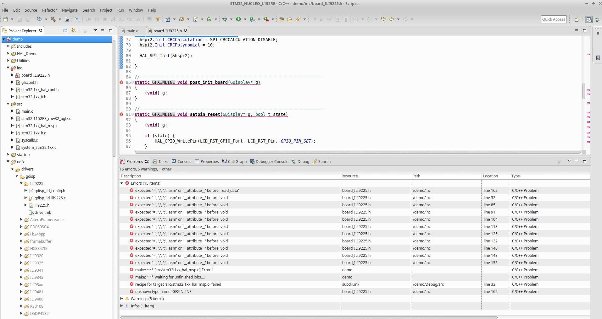
Hi! It looks that these files are indeed missing. Searching for the pattern "9225" doesn't find any matches on my filesystem. $ find ugfx -name "*9225*" ugfx/drivers/gdisp/ILI9225 ugfx/drivers/gdisp/ILI9225/ili9225.h ugfx/drivers/gdisp/ILI9225/gdisp_lld_ili9225.c $ So I tried to set up the board file by my own. As mentioned I disabled the filter in properties -> C/C++ General -> Paths and Symbols -> Source Location for the ILI9225 driver directory and added drivers/gdisp/ILI9225 to properties -> C/C++ General -> Paths and Symbols ->Includes. Then I copied and modified a board file using a different ili driver and enabled the gdisp driver by setting #define GFX_USE_GDISP GFXON . Unfortunately, I fail now to build since I a get a bunch of new compile errors. Obviously, the compiler doesn't recognize GFXINLINE which is defined in src/gfx_complilers.h. Fixing these bugs by just replacing GFXINLINE by inline circumvents the particulars problems but brings a bunch of new ones since the compiler doesn't recognize the types GDisplay or bool_t. What did I wrong? By the way. I'm not sure if it's the right place here but I found a bug in drivers/gdisp/ILI9225/gdisp_lld_ili9225.c line 51: #define write_data_repeat(g, data, count) { int i; for (i = 0; i < count; ++i) write_data (g, data) } misses a semicolon. Please inform me about your desired way to report bugs in future. Last but not least I have a question regarding the functions static GFXINLINE void write_index(GDisplay* g, uint16_t index) and static GFXINLINE void write_data(GDisplay* g, uint16_t data) I guess the latter is used fr display communication. So in my case I need to implement the code for SPI communication there, right? Whats the purpose of the first one and is it in my case necessary to implement?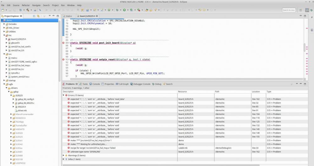
-
Mutiple definitions uGFX + Eclipse + STM32L1
tombalabomba replied to tombalabomba's topic in Support
Hi! Many thanks for clarification! By the way. Are the source files used in the tutorial available somewhere? Since, there are no board files available for the ILI9225 driver I wonder if you could share the one you used in the example. Hence, it would make things easier for understanding how to properly implement by the hardware abstraction by adapting the sources to my particular board. -
Mutiple definitions uGFX + Eclipse + STM32L1
tombalabomba replied to tombalabomba's topic in Support
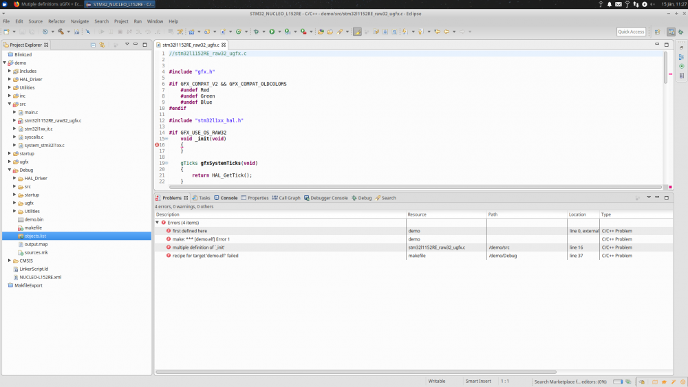
Hi! As I mentioned in my previous post, I get a bunch of additionally HAL error as soon as I modify stm32f439i_raw32_ugfx.c . The HAL errors vanish as soon as I close and reopen the project. As I figured out now these HAL errors were not really the problem since they don't show up in the build output. Hence, it looks like this is a feature from the IDE telling the user that there is something missing for building the particular source file. Unfortunately, for me it was rather a burden than a feature since it distracted me from the central problem. You are right, remove _init(void) from stm32l1152RE_raw32_ugfx.c does fix the error in first place. Apparently, this function is not used in gfxInit() so guess it's no big deal to remove it. But I'm really interested in the root cause of this error in oder to understand how I can prevent such issues in future.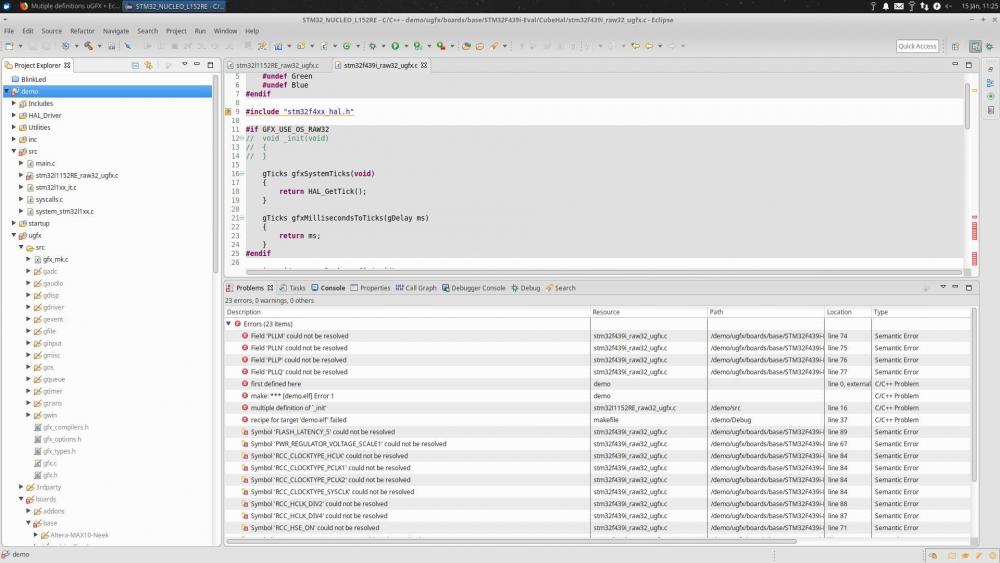
-
Mutiple definitions uGFX + Eclipse + STM32L1
tombalabomba replied to tombalabomba's topic in Support
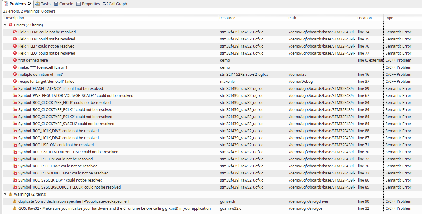
Hi! The specific error of a multiple defined _init() function still persists. What changes that I get now the HAL erros additonally. After project clean I get the following compiler output: Right below you can find the error output. The interesting part is that I get now the HAL errors additionally. These errors appeared when I modified stm32f439i_raw32_ugfx.c the first time. So, it looks like the compile tries to compile this file which should be prohibited by setting the filter in the source location tab. Unfortunately, project clean and index rebuild does not change anything. You can find my project in the attachment. Many many thanks for supporting. demo.zip
-
Mutiple definitions uGFX + Eclipse + STM32L1
tombalabomba replied to tombalabomba's topic in Support
Hi! This was already one of my thoughts. As I mentioned in my previous post commenting or deliting _init() in stm32f439i_raw32_ugfx.c doesn't fix the problem of getting the error of a multiple defined _init(). That seems odd to me since I'm pretty sure that there is no additional _init() defined in the sources. Additionally, I get now a lot of errors originating from non defined ST32F4 Hal symbols. This should not be the case since stm32f439i_raw32_ugfx.c is excluded from build. The fact that modification of stm32f439i_raw32_ugfx.c brings in this bunch of additional errors is an indication for me that the IDE is buggy. Apparently, source code exclusion doesn' t work out. -
Mutiple definitions uGFX + Eclipse + STM32L1
tombalabomba replied to tombalabomba's topic in Support
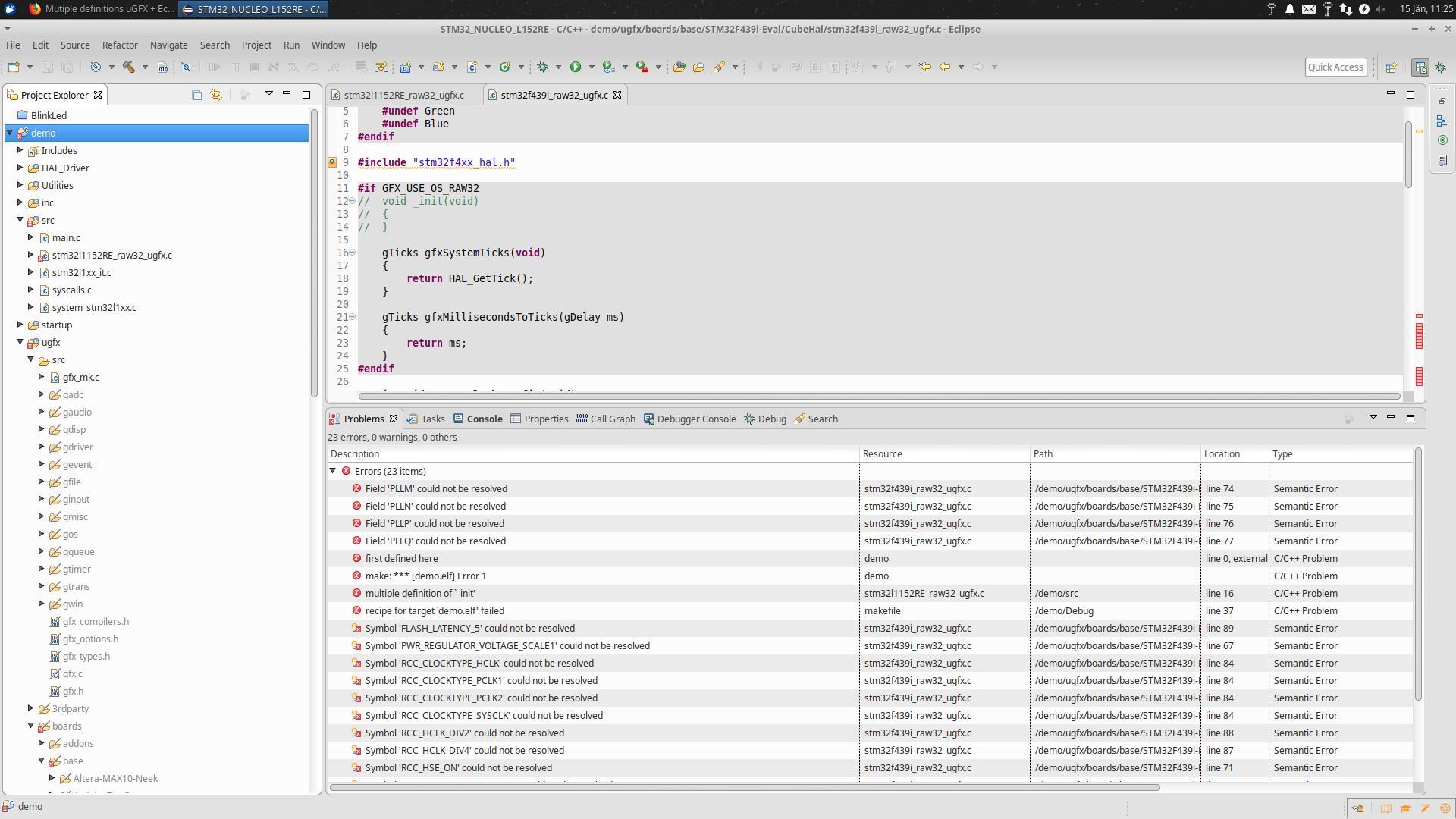
Hi! As mentioned, I modified the example code so that it fits to my CPU. Basically, the only difference to the example code in demo/ugfx/boards/base/STM32F439i-Eval/CubeHal/stm32f439i_raw32_ugfx.c is that the clock configuration is different to the Cortex M4 HAL. //stm32l1152RE_raw32_ugfx.c #include "gfx.h" #if GFX_COMPAT_V2 && GFX_COMPAT_OLDCOLORS #undef Red #undef Green #undef Blue #endif #include "stm32l1xx_hal.h" #if GFX_USE_OS_RAW32 void _init(void) { } gTicks gfxSystemTicks(void) { return HAL_GetTick(); } gTicks gfxMillisecondsToTicks(gDelay ms) { return ms; } #endif static void SystemClock_Config(void); void Raw32OSInit(void) { HAL_Init(); SystemClock_Config(); } /** * @brief System Clock Configuration * The system Clock is configured as follow : * System Clock source = PLL (HSE) * SYSCLK(Hz) = 32000000 * HCLK(Hz) = 32000000 * AHB Prescaler = 1 * APB1 Prescaler = 1 * APB2 Prescaler = 1 * HSE Frequency(Hz) = 8000000 * PLLMUL = 12 * PLLDIV = 3 * VDD(V) = 3.3 * Main regulator output voltage = Scale1 mode * Flash Latency(WS) = 1 * @param None * @retval None */ static void SystemClock_Config(void) { RCC_ClkInitTypeDef RCC_ClkInitStruct; RCC_OscInitTypeDef RCC_OscInitStruct; /* Enable Power Control clock */ __HAL_RCC_PWR_CLK_ENABLE(); /* The voltage scaling allows optimizing the power consumption when the device is clocked below the maximum system frequency, to update the voltage scaling value regarding system frequency refer to product datasheet. */ __HAL_PWR_VOLTAGESCALING_CONFIG(PWR_REGULATOR_VOLTAGE_SCALE1); /* Enable HSE Oscillator and activate PLL with HSE as source */ RCC_OscInitStruct.OscillatorType = RCC_OSCILLATORTYPE_HSE; RCC_OscInitStruct.HSEState = RCC_HSE_ON; RCC_OscInitStruct.PLL.PLLState = RCC_PLL_ON; RCC_OscInitStruct.PLL.PLLSource = RCC_PLLSOURCE_HSE; RCC_OscInitStruct.PLL.PLLMUL = 12; RCC_OscInitStruct.PLL.PLLDIV = 3; HAL_RCC_OscConfig(&RCC_OscInitStruct); //HAL_PWREx_EnableOverDrive(); /* Select PLL as system clock source and configure the HCLK, PCLK1 and PCLK2 clocks dividers */ RCC_ClkInitStruct.ClockType = (RCC_CLOCKTYPE_SYSCLK | RCC_CLOCKTYPE_HCLK | RCC_CLOCKTYPE_PCLK1 | RCC_CLOCKTYPE_PCLK2); RCC_ClkInitStruct.SYSCLKSource = RCC_SYSCLKSOURCE_PLLCLK; RCC_ClkInitStruct.AHBCLKDivider = RCC_SYSCLK_DIV1; RCC_ClkInitStruct.APB1CLKDivider = RCC_HCLK_DIV1; RCC_ClkInitStruct.APB2CLKDivider = RCC_HCLK_DIV1; HAL_RCC_ClockConfig(&RCC_ClkInitStruct, FLASH_LATENCY_1); } As I mentioned above I did a grep on my working directory searching the pattern "_init(void)". Besides stm32l1152RE_raw32_ugfx.c the only matching location is /ugfx/boards/base/STM32F439i-Eval/CubeHal/stm32f439i_raw32_ugfx.c. So I commented void _init(void) in stm32f439i_raw32_ugfx.c but the error still persists. Additionally I get a bunch of new compile errors since a lot of HAL symbols used in stm32f439i_raw32_ugfx.c can not be resolved. I really wonder how can this be since this file is exclude from build. Unfortunately, right clicking ->Resource Configuration->Exclude from Build doesn't change anything. -
Hi! First of all I have to apologize, the question I have exposes me to be quite a newbie. I'm using openSTM system workbench (Neon.3 Release (4.6.3)) and desperately try to get a bare-metal application using a STM32L1 nucleo board (CubeMX HAL) and ILI9225 TFT running. Since this IDE is essentially based on Eclipse I followed the guide https://wiki.ugfx.io/index.php/Using_Eclipse to set up the project. So I did the following steps. Library Import : demo -> Import ugfx Configure Include Paths : demo -> properties -> C/C++ General -> Paths and Symbols -> Includes : adding /demo/ugfx to all languages and configurations Specify Sources : demo -> properties -> C/C++ General -> Paths and Symbols -> Source Location : adding /demo/ugfx, filter everything except /demo/ugfx/src/gfx_mk.c Copying /demo/ugfx/ gfxconf.example.h to /demo/inc/gfxconf.h, enabling raw32 by #define GFX_USE_OS_RAW32 GFXON Copying and modifing /demo/ugfx/boards/base/STM32F439i-Eval/CubeHal/stm32f439i_raw32_ugfx.c to /demo/src/stm32l1152RE_raw32_ugfx.c Including "gfx.h" in and calling gfxInit() in main.c In stm32l1152RE_raw32_ugfx.c there is no code specified in _init(), but it should compile without errors. Unfortunately, it doesn't since I get the following error message. So it looks there is a problem with multiple definitions of void _init(void). I did a grep on my working directory and the only two matches was /demo/ugfx/boards/base/STM32F439i-Eval/CubeHal/stm32f439i_raw32_ugfx.c and /demo/src/stm32l1152RE_raw32_ugfx.c. Since the first is excluded from build I doubt that there is really a problem with multiple definitions here. Has anyone faced a similar problem yet? Any help is kindly appreciated.
-
It lookls like this is a quite good starting point. Many Thanks!