

jrelder
-
Posts
17 -
Joined
-
Last visited
-
First off I just want to say that with my following discussion I am not saying you are wrong, I just don't fully understand how the points you mention can be true that's all, and I'll try and explain why. Before I do though, in answer to your question, I am running it in 16bit mode, the wiring is setup for 16bits (lines D0 to D15 are connected) and so are my FSMC/GPIO settings. Although, I do not know what interface setting the LCD is primed for (the driver manual mentions four pins PS0 - PS4 which set the interface mode) however my LCD board doesn't have any exposed jumpers or solder bridges with which I can modify this). I am assuming it is primed for 16bit mode for two reasons - 1. the amazon listing from where I bought the LCD has a reviewer which mentions they have this display working in 16bit mode, 2. it seems to work almost fully which I would guess wouldn't be true if I was trying to run an LCD setup for 8bits in 16bit mode?. As for your reasons, I understand, but it seems that point 2. contradicts point 1. It doesn't seem to be anything to do with position on the screen from what I have seen. I.e. I have had correct drawing on the position of the screen where the uGFX logo is distorted when it comes to the shapes/lines which are displayed after the logo. Aside from this, I also know that if I change the TB to 0, and the AM and ID, I can get the correct uGFX logo, and this is without changing any of the wiring so this leads me to believe the wiring is correct? As for point 3, rotating by 180 degrees does not fix the uGFX logo issue, the only way I have managed to fix that is by changing both a combination of the TB, AM and ID values (but at the cost of the yellow frame being incorrect). I personally think that changing the TB and it resulting in fixing the uGFX logo seems weird, as the TB value seems to be the value for mirroring on the plane of the horizontal axis of the display, but obviously the uGFX logo is positioned on this axis in the centre of the screen vertically, so this shouldn't have any effect (I hope you understand what I mean), it should be the RL setting if any which would have an effect. Anyway, I believe that I am possibly confusing the situation now by posting so many comments, so I think what I will do is try to write a comment which shows the settings of the TB, AM and ID values along with the output on the LCD, for both the correct uGFX logo and the correct shapes. I have checked and physically disconnected and rewired all pins from scratch, multiple times, so I do believe the wiring is correct, unless the pinout I have used (my breakout board doesn't have any writing on it to describe the pin functions) is incorrect. But it seems that if I switch wires on the D0-D15 lines from the current setting, I get a blank white screen with no display. This post was just to explain my thoughts, I will shortly post to provide a comprehensive explanation of the different TB, AM and ID settings and the corresponding display output. Please bear with me.
-
Thanks for the advice. Actually the previous images were already at a very low speed (HCLK 8MHz) and with the address and data setup times at their slowest values (15 and 255). I have tried a HCLK of 2MHz and it makes no difference, the problems still occur I have tried swapping D0 and D1 as you have suggested and the result is that the screen just stays a blank white, showing no image at all, leading me to think that the pins are correctly wired currently. I have triple checked the wiring a few times now, but I will definitely check it again. Its strange because previously with other settings of AM, ID and TB I had the correct uGFX logo as you saw, but incorrect yellow frame. But when changing the TB to its correct value of 1, and changing the rotation such that AM and ID are 0 and 00 I get the incorrect uGFX logo and correct yellow frame (aside from the overshoot which you correctly pointed out). One other thing, originally, before I changed the rotation and consequently the AM/ID values, I was looking to just change the RL and TB settings to flip the image in the X/Y as it seemed mirrored. However, I noticed that on the datasheet for the SSD1289 driver the RL setting has no effect in RAM mode, the datasheet quotes: So I could not use the RL bit to flip the image in the vertical axis as I thought it needed to be, hence the requirement to use the AM and ID settings instead. I don't know if this is a normal limitation or not for display drivers?
-
Yes, sorry here they are

-
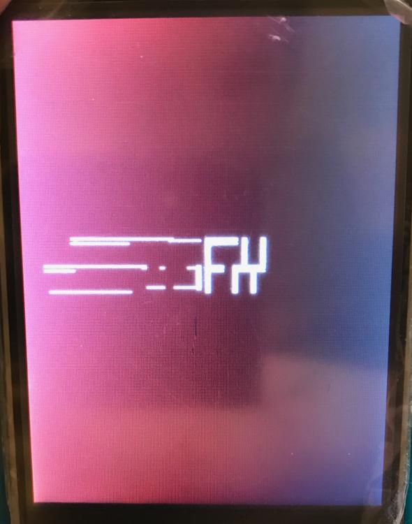
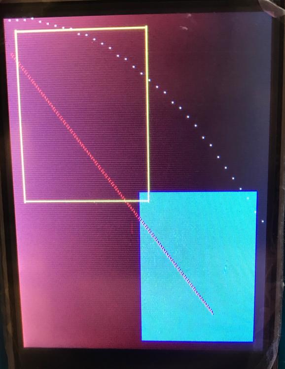
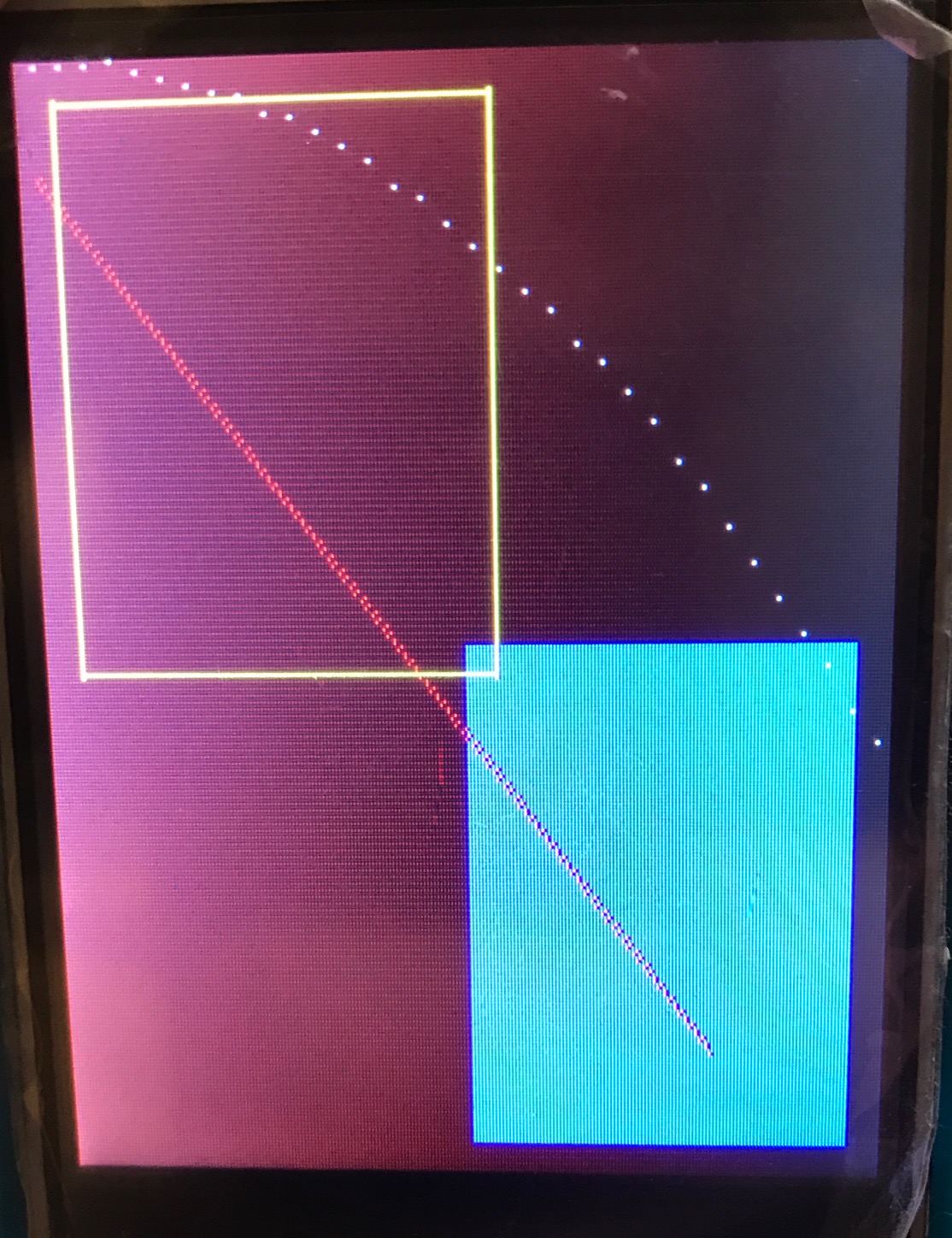
I have realised that I can get the correct image, with the red line, white dotted curve, blue filled rectangle and yellow frame, if I set the rotation to 180 and set the ID to 00 and AM to 0. However, the uGFX text is distorted... Please see the attached images.

-
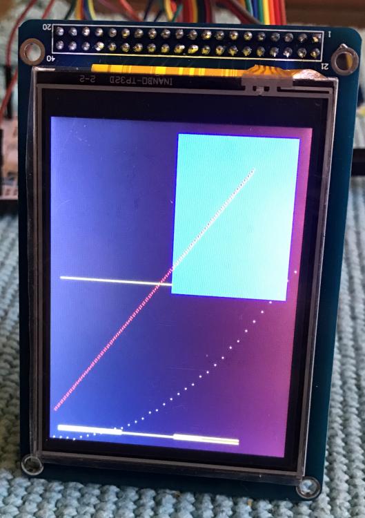
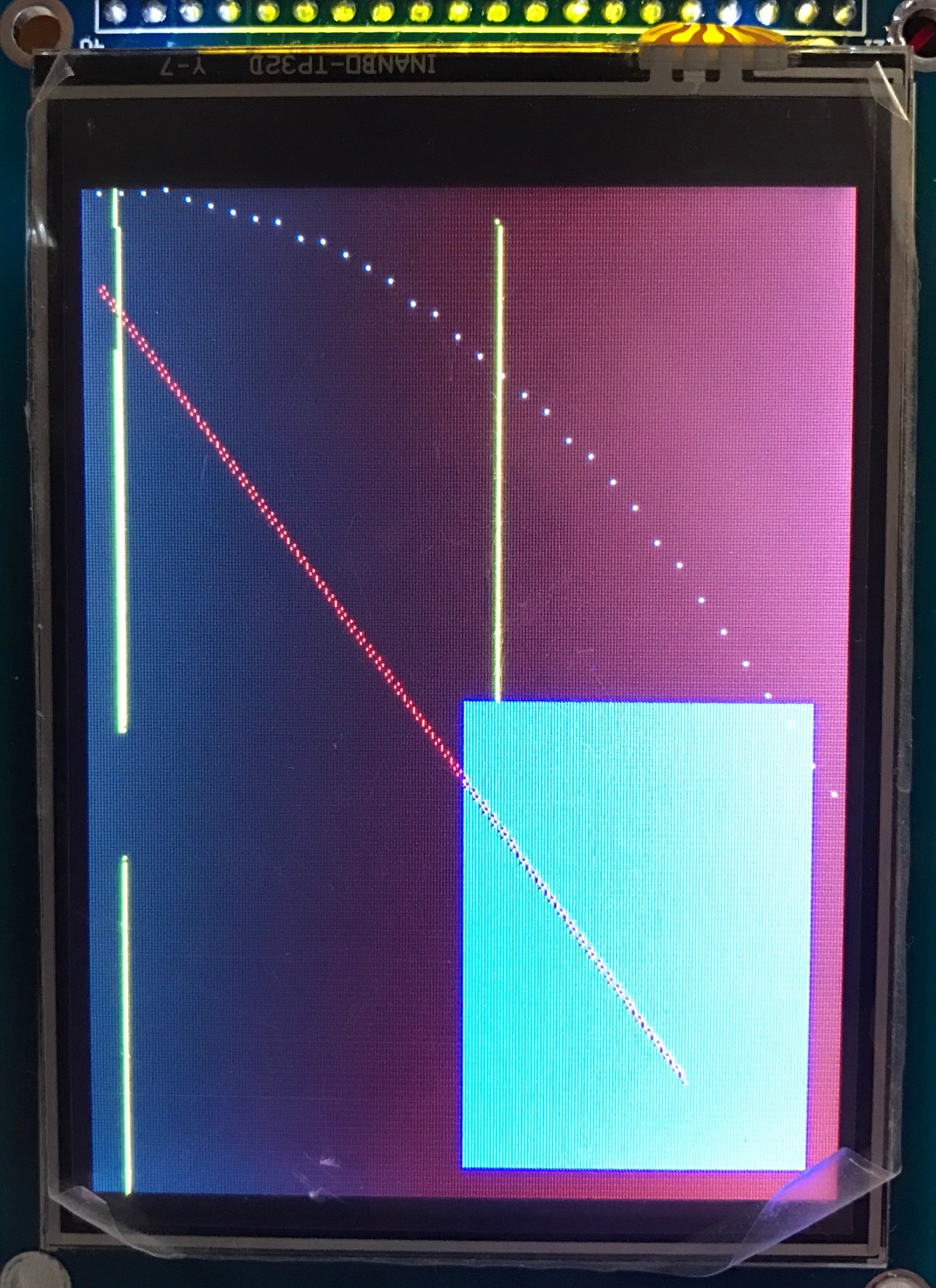
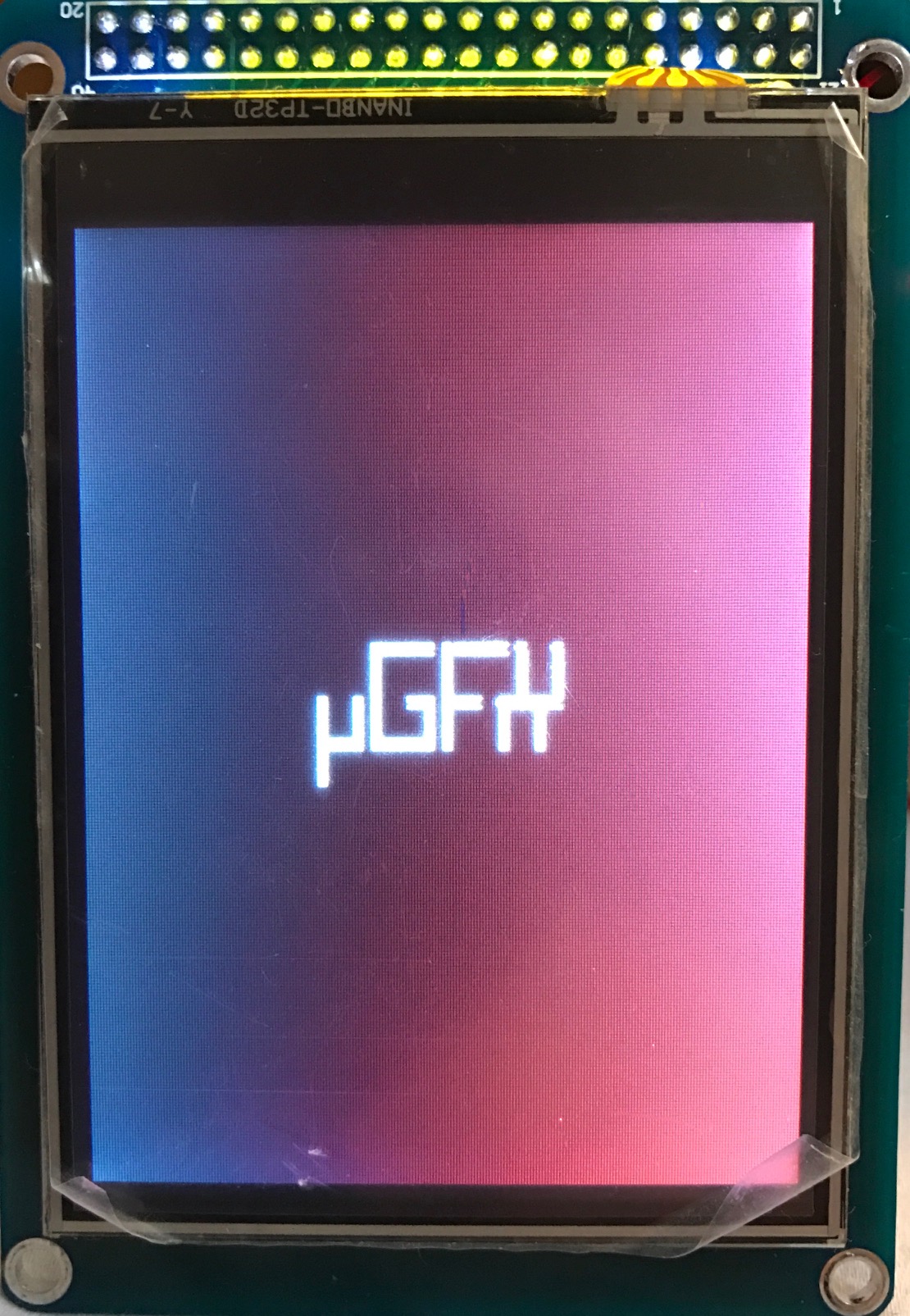
Thanks for the advice @inmarket, it really helped. I believe I am almost there now after changing the initialisation. I have the correct uGFX logo I believe, the red line and the blue rectangle look correct also. The only issue is the yellow frame, please see the attached images:


-
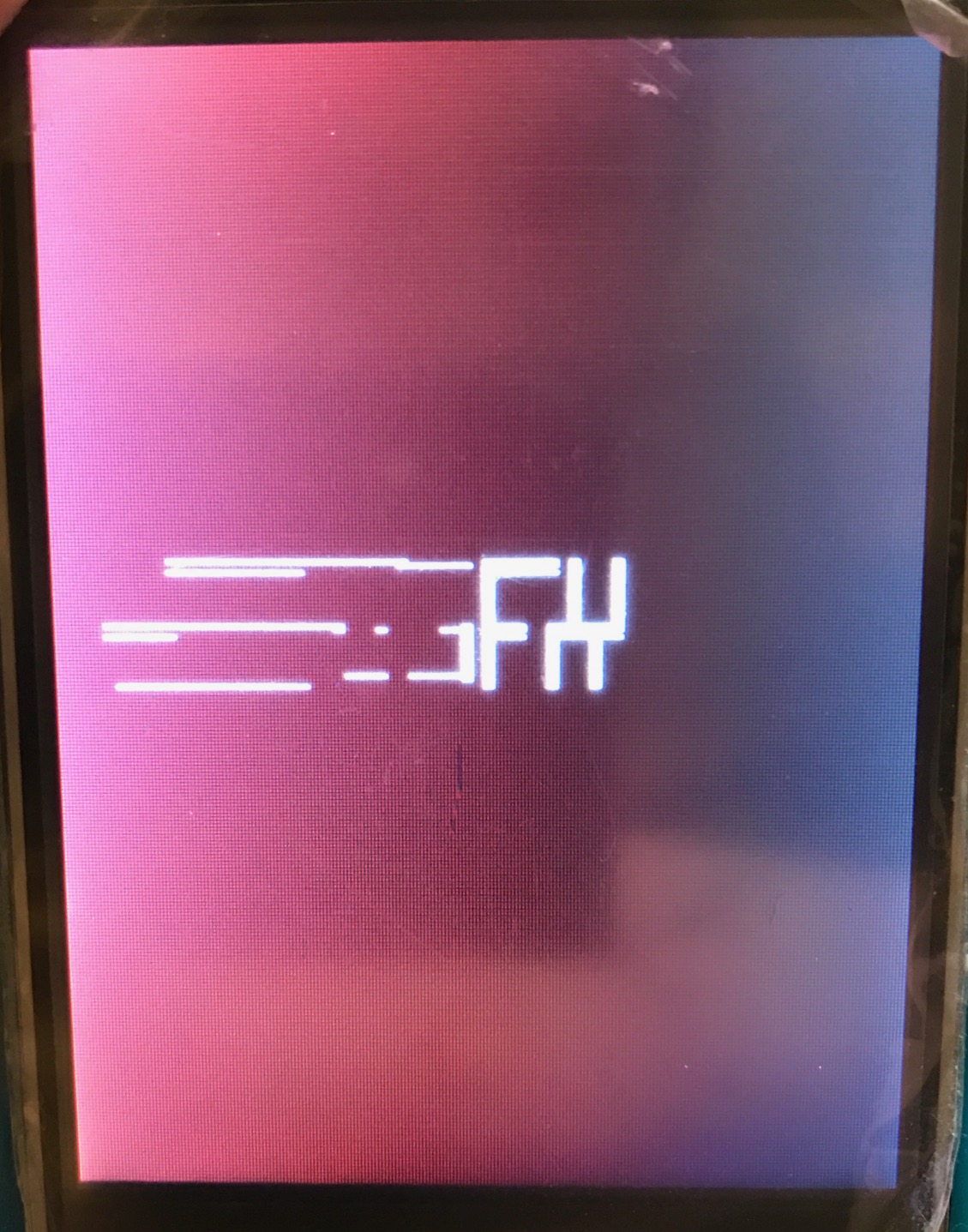
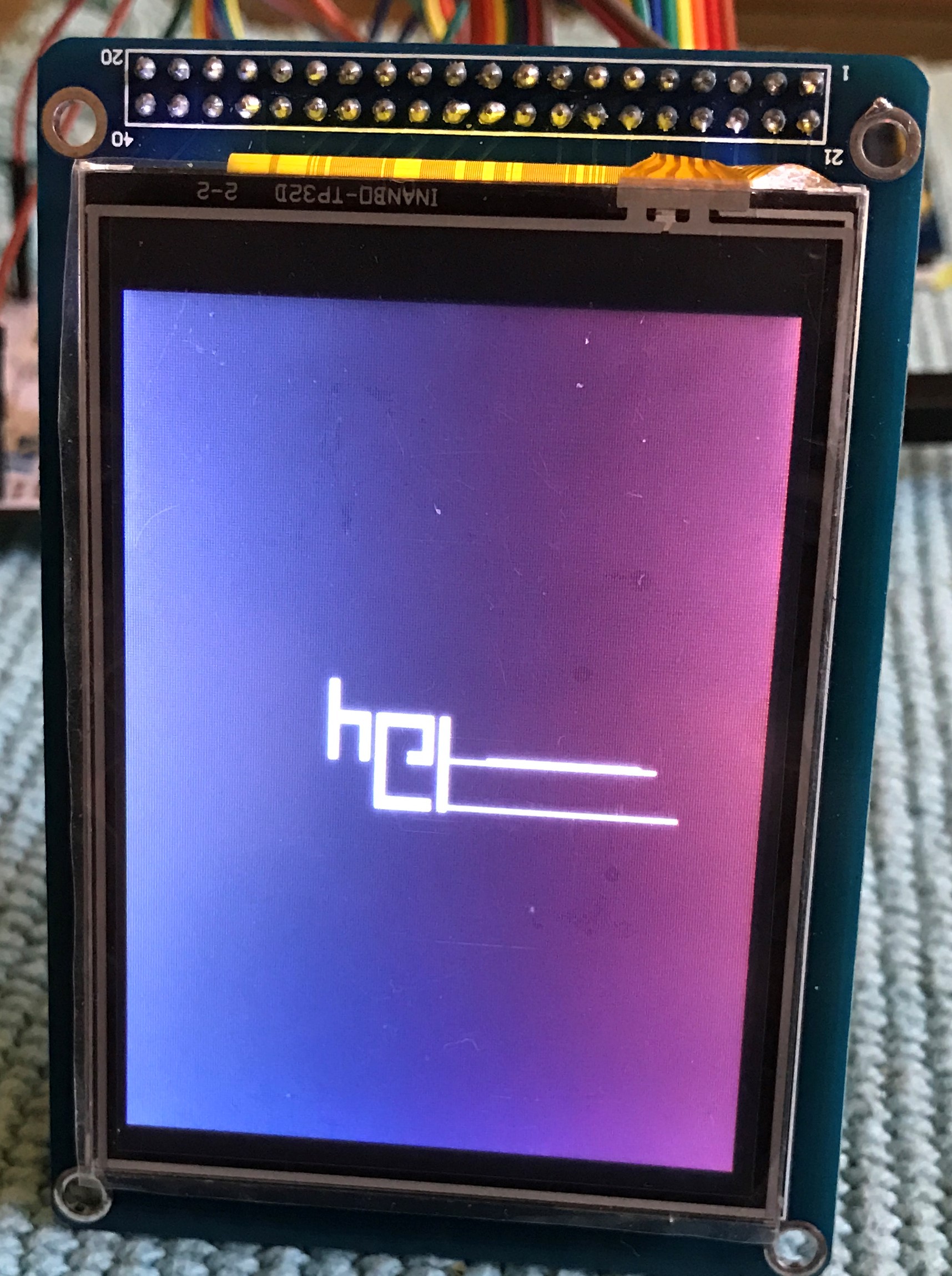
Okay, so I have an update. Today I received the replacement LCD, however it still did not work. So I was trying a few things, and due to advice from the STM32 forum, I changed the LCD Register Select to A16. Apparently the addresses I used (REG: 0x60000000, RAM: 0x6002000) are the A16 address line. Now this doesn't make sense to me as I don't understand how the addresses and registers work (I've been looking for guides, if you know any good links please let me know), but by changing this I have finally got an output on the LCD. I have also changed the frequency to 8MHz just until I get everything working as it should. Anyway, I believe the output is still wrong, as the yellow box seems to be distorted and the ugfx writing on startup is also distorted. Attached are the pictures of the display (sorry about the lighting, it makes the colours look a bit strange but this is not the case in reality), I believe I need to flip the Y axis, but what about the other issues, I don't suppose anyone has an idea as to why this is happening? Also I was searching google and the wiki for an example image of how this demo should look, but I couldn't find one. I believe this is important for any users of the library to be able to verify the demo does in fact work as it should, so maybe it would be an idea to add some images either in the demo folders of the library or on the wiki. I know it can be inferred from the code, but I still think it would be helpful to have example images.

-
I've double checked the reset pin and it is correct I believe (see below for more info on this). I don't have the tools to check the bus though, so I'll have to problem solve another way. 1. The clock speed is perhaps high, but I thought that the calculated values for DATAST and ADDST take account of this? STM32CubeMX has set these automatically at values of 255 and 15. 2. I didn't realise that, that is definitely something I should consider. 3. I believe the reset pin is correct, I've checked the datasheet and it says: RES - System Reset Pin - Connect to V(DDIO) when not used. I take it this means when not activating a reset it should be set to 'high'. 4. I've been through my code and I cannot see anything. Also I haven't added any extra outputs/inputs other than the LCD, and I haven't added any functions/code other than the uGFX Basic demo stuff. So I believe I'm okay on this one. 5. This point is interesting and I have considered it. The datasheet for the driver IC discusses 4 pins which are for interface selection. However on my LCD board these pins haven't been broken out into any kind of jumpers, in fact there are no jumpers at all on the board. However, the amazon description of the listing from where I bought it states: "support 8/16bit data interface" and a reviewer has said they used it in 16bit parallel mode. So I would think its already activated for 16bit mode, however I don't see how it can be activated for both 8 and 16bit mode as the datasheet details different pin settings for these. Any just to conclude, I have since decided I would verify that the display is not faulty by connecting it to an Arduino in 8bit mode and running a demo. Now unless the issue discussed in point 5 (maybe its not activated for 8bit mode) is true, the LCD is faulty as all I get is the same white screen. I have triple checked the connections for the Arduino and the library pin settings, they are all correct. So I believe after all this effort I will conclude that the LCD is faulty and I'll order another instead.
-
Another question I have, is how important is the LCD RST pin? Could this be causing the issue perhaps? For now I have connected it as follows: GPIO Pin: PC1 Setup for GPIO output Pin State: High Mode: Output Push Pull Pullup/Pulldown: None Speed: Low I read that it is not important where it is connected and that it could be connected to the STM32 boards reset pin. I chose to connect it to PC1 and I have defined the reset function as follows: #define LCD_ENABLE_RESET 1 #define LCD_DISABLE_RESET 0 static GFXINLINE void setpin_reset(GDisplay *g, bool_t state) { (void) g; if (state == 1) HAL_GPIO_WritePin(GPIOC, GPIO_PIN_1, GPIO_PIN_RESET); else if (state == 0) HAL_GPIO_WritePin(GPIOC, GPIO_PIN_1, GPIO_PIN_SET); }
-
Thanks, although it turned out that even after all this, and the code compiling correctly with no errors/warnings, the screen of the LCD just stayed blank (white). So I have gone back to basics and instead of my own GUI, I'm just trying to get the Basic demo working for now (I'm having some troubles with that, blank white screen): https://community.ugfx.io/topic/684-basic-demo-blank-white-screen/ Any help on this would be greatly appreciated, thanks
-
Hi, So first of all I'd like to explain my current hardware/software setup. I am using an STM32F413 Nucleo board with an SSD1289 based LCD display. I have started a new project in Keil, in which he first thing I did is to use STCubeMX to setup the FSMC for the display and the HCLK to 100MHz. I then followed the wiki guide to import the gfx_mk.c, gfxconf.h, board_SSD1289.h and gdisp_lld_SSD1289.c files into my project. I edited the board_SSD1289_template.h file for the following: #define GDISP_REG ((volatile uint16_t *) 0x60000000)[0] /* RS = 0 */ #define GDISP_RAM ((volatile uint16_t *) 0x60020000)[0] /* RS = 1 */ #define FSMC_BANK 0 static GFXINLINE void write_index(GDisplay *g, uint16_t index) { (void) g; GDISP_REG = index; } static GFXINLINE void write_data(GDisplay *g, uint16_t data) { (void) g; GDISP_RAM = data; } static GFXINLINE void setreadmode(GDisplay *g) { (void) g; FSMC_Bank1->BTCR[FSMC_BANK+1] = FSMC_BTR1_ADDSET_3 | FSMC_BTR1_DATAST_3 | FSMC_BTR1_BUSTURN_0; /* FSMC timing */ } static GFXINLINE void setwritemode(GDisplay *g) { (void) g; FSMC_Bank1->BTCR[FSMC_BANK+1] = FSMC_BTR1_ADDSET_0 | FSMC_BTR1_DATAST_2 | FSMC_BTR1_BUSTURN_0; /* FSMC timing */ } static GFXINLINE uint16_t read_data(GDisplay *g) { (void) g; return GDISP_RAM; } This was done by referencing how it is done in the board_SSD1289_stm32f4discovery.h file (obviously ignoring the FSMC init as this is handled elsewhere, and also the DMA as I do not use it). As I am running it RAW/Baremetal, I have defined the following two functions in my main.c file: gfxSystemTicks and gfxMillisecondsToTicks. The above compiled fine, so now it was time to try one of the demos from the library. I chose the Basics demo. The first thing I did is to take the gfxconf.h from the Basics demo to replace my previous template file, and ensure I added the line #define GFX_USE_OS_RAW32 TRUE. Lastly I edited my main loop as follows: int main(void) { coord_t width, height; coord_t i, j; /* MCU Configuration----------------------------------------------------------*/ /* Reset of all peripherals, Initializes the Flash interface and the Systick. */ HAL_Init(); /* Configure the system clock */ SystemClock_Config(); /* Initialize all configured peripherals */ MX_GPIO_Init(); MX_FSMC_Init(); // Initialise uGFX gfxInit(); // Get the screen size width = gdispGetWidth(); height = gdispGetHeight(); // Code Here gdispDrawBox(10, 10, width/2, height/2, Yellow); gdispFillArea(width/2, height/2, width/2-10, height/2-10, Blue); gdispDrawLine(5, 30, width-50, height-40, Red); for(i = 5, j = 0; i < width && j < height; i += 7, j += i/20) gdispDrawPixel(i, j, White); /* Infinite loop */ while (1) { gfxSleepMilliseconds(500); } } Now after compiling successfully with no errors and flashing my board, I just get a blank white screen (nothing at all happens). I believe it is all wired correctly and I have double checked, so can anyone see any errors in my software setup? Thanks in advance!
-
I believe I may have fixed this, after noticing this post: https://community.ugfx.io/topic/284-custom-online-converted-font-not-supported-by-mcufont/ It seems that as I had added the font files to the project tree in Keil, then Keil was trying to compile them out of context. So I have removed them from the tree, but the rsc folder is in the include path such that the correct files discover them. I think this has solved my problem, now I get to the linking stage and then receive the following error: ColourDIS2\ColourDIS2.axf: Error: L6218E: Undefined symbol GMOUSEVMT_OnlyOne (referred from gfx_mk.o). EDIT: Solved by setting GINPUT_NEED_MOUSE to FALSE. I believe the error is because I was asking for the mouse but I hadn't defined anything in my code for the hardware configuration of the touch screen.
-
I've removed that from my includes but the error is still there. I think I''m confused as to the reason for the includes, and maybe I've included the others incorrectly too. When you say in the guide "we need to add the top level uGFX library directory to the compiler include path" do you mean the ugfx group directory which we have just created or do you mean the directory location from where we imported the gfx_mk.c file (which was obtained from the gfx/src folder)? This may sound basic but I've never used an IDE before now, and it's been a long time since I've coded in any other language than Python. In which I would use includes to specify the location of the header file relative to the position of the current file...
-
Oh and just to mention in the above you will notice the font files displayed under rsc are DejaVuSans16, 20_aa and 32_aa. I changed the fonts in uGFX Studio to see if the error happens with all of them and it does. I just didn't delete the font files from the rsc folder that's all.
-
Haha no I haven't got that far yet, I'm hoping it won't take me long to learn how to use custom fonts though. No I haven't actually displayed anything on my hardware yet. Iliterally followed the guide to using/configuring uGFX with Keil/Hardware (https://wiki.ugfx.io/index.php/Using_Keil_µVision_5_MDK-ARM) and checked it compiles correctly as discussed in the guide. Then I imported my output files and any necessary library files, as created by uGFX Studio, and everything else is fine except for this one error about the font file not being compatible. It doesn't seem to complain about not finding the font file or mcufont though. Also I wanted to point out that although i'm using a default font, for some reason uGFX Studio has output a userfonts.h file and the DejauSans12.c file. Aso and the gfxconf.h file defines user fonts as true. I thought this was a bit strange considering I used the inbuilt fonts in uGFX Studio? Anyway attached are my project tree and the include directories.
.thumb.png.9adf8e1287f0c4cf683bb8d8b5681628.png)
.thumb.png.9ad92fa86d12e63fefb20e79a2e1185b.png)
-
Hi Joel, thanks for the prompt reply! Sorry if this sounds stupid, but what do you mean by the built in fonts? I believe the font I've used in my project DejaVuSans12, is a built in uGFX font.


.png.4d31ad261236c0e45adb574bf9df56ab.png)
.png.0af6535377771d2e9841cd6de22f4191.png)